# Glesys documentation
Learn how to build, deploy, and scale applications on Glesys with clear tutorials, practical guides, reference material, and example code across our products.
***
### Products
We offer a wide range of cloud, infrastructure, and managed services — from compute, storage, databases, and connectivity to bare metal and data center solutions.
Compute
Accelerate your build and release process with scalable cloud computing products that suit projects of any size, from large to small and everything in between.
With Glesys, you can depend on our expertise in bare-metal technology. Host your website, deploy your robust infrastructure, or tailor your machine to fit your projects.
Use S3-compatible Object Storage to reliably store and access unlimited data in the cloud or utilize network-based File Storage and Archive Storage volumes.
Managed services allow you to delegate infrastructure and support tasks, enabling you to concentrate on strategic priorities without the responsibility of operational complexity.
With our connectivity products, you can access new markets through our global ecosystem and expand your IT infrastructure rapidly and securely on demand.
### Developer tool
Glesys provides powerful developer tools, including a full-featured API and Terraform Provider, enabling automated management of infrastructure and seamless integration into your workflows.
API
Using the API, you can manage everything—from organizations and projects to servers, IP addresses, and more—entirely programmatically.
The Glesys Provider lets you manage supported resources once configured with valid credentials, with detailed guidance available through the resource navigation menu.
### Support
The support section gives you clear guidance on payments, contract terms, service termination, and real-time status updates, ensuring you can manage your services confidently and resolve issues quickly.
Payment options
We support payments via bankgiro, domestic and international transfers, credit cards, and PayPal, providing multiple secure options for settling invoices efficiently.
Service terms vary: cloud uses pay-as-you-go with minimal commitment, while dedicated servers, connectivity, and colocation follow monthly billing with binding periods.
Service termination requires notice; non-payment doesn’t cancel services. Delete cloud servers in the control panel, while monthly services require written notice.
Our status page provides real-time updates on service health, ongoing incidents, and scheduled maintenance, helping you stay informed about platform performance and availability.
Contact support for fast, reliable assistance with services or technical issues—our team is ready to help you resolve questions and keep your operations running smoothly.
# Data center overview
Our data centers in Sweden, Finland, and partner sites in the Netherlands, Norway, and the UK deliver secure, flexible, scalable, energy-efficient solutions for your hybrid data and colocation needs.
***
### Our own data centers
Falkenberg data center
Our Falkenberg facility on Sweden's west coast delivers secure, scalable colocation, dedicated servers, GPU hosting, and cloud infrastructure with 2N redundancy.
Oulu data centers in Finland provide secure colocation, scalable compute, renewable energy, and advanced redundancy to support hosting and GPU services.
Pori data center in Finland provides secure colocation, scalable compute, energy-efficient infrastructure, and redundancy to support reliable hosting services.
Tampere data center in Finland provides secure colocation, scalable compute, high-density GPU-ready infrastructure, and redundancy to support demanding workloads.
Our Amsterdam Equinix facility offers dense networking, extensive peering, and ultra-low latency, serving as a powerful gateway for expanding digital presence.
Our London Equinix facility delivers world-class network density, extensive international peering, and exceptional speed to expand digital reach at global scale.
Our Oslo partner facility provides renewable-powered infrastructure, enabling high-performance cloud and network operations and connecting you to Europe’s growing digital region.
Frankfurt data centers in Germany provide secure, highly available colocation with scalable infrastructure, redundancy, and 24/7 operations near DE-CIX.
# DC Oulu Elektroniikkatie 5
Site address: Elektroniikkatie 5, 90590 Oulu, Finland
***
Our DC Oulu Elektroniikkatie 5 is designed to deliver reliable operations, energy efficiency, and robust security. With total power capacity of 0.4 MW, up to 11 kW per rack, and N+2 UPS redundancy backed by generators, we support colocation, dedicated servers, and GPU hosting. Advanced environmental controls, including temperature and humidity regulation and Argonite gas fire suppression, ensure operational stability. Network, power, and remote hands and eyes services are engineered to meet demanding workloads, all while operating on 100% renewable energy for sustainable performance.
### Power
| | |
| ----------------------------- | --------- |
| Total power capacity | 0.4 MW |
| Max rack density | 11 kW |
| UPS redundancy | N+2 |
| Backup power type | Generator |
| Backup power redundancy | No |
| Utility connection redundancy | 2+N |
| PUE | 1.3 |
### Cooling
| | |
| ----------- | ------- |
| Temperature | 20–30°C |
| Humidity | 20–80% |
### Fire prevention & suppression
| | |
| ---------------- | --------------- |
| Detection system | Smoke detection |
| Gas suppression | Agronite |
### Security
| | |
| ----------------------------- | ----------------------- |
| Bullet proof glass checkpoint | No |
| Mantrap | No |
| CCTV | Yes (4 weeks retention) |
| Security guards | Round guard |
| Onsite personnel 24/7 | No |
| Biometric | No |
| Burglar resistance | Not specified |
| Authentication factors | Access card, PIN |
### Amenities
| | |
| ------------------ | --- |
| Meeting rooms | No |
| Break rooms | No |
| Onsite car parking | Yes |
| Spare parts | Yes |
| Staging room | No |
| Office space | No |
| WiFi access | Yes |
| Remote hands 24/7 | Yes |
| Remote eyes 24/7 | Yes |
### Services
| | |
| ----------------- | --- |
| Colocation | Yes |
| GPU hosting | Yes |
| Dedicated servers | Yes |
| VPS | Yes |
| Managed hosting | Yes |
| Extended SLA | Yes |
| Network services | Yes |
| Remote hands | Yes |
| Remote eyes | Yes |
### Colocation
| | |
| -------------------------- | ------------- |
| Suites/Cages | No |
| Sub-racks | No |
| Rack height | 42U |
| Rack width/depth | 800 x 1200 mm |
| Rack mounted PDU | Modular |
| Communication entry points | 2 |
| Meet-me rooms | 0 |
| Fiber patch panel | Yes |
| Copper patch panel | No |
### Network connectivity
| Provider / exchange | ASN | Dark fibre | Internet exchange | Wavelength | IP transit | Internet | Ethernet transport |
| ------------------- | --- | ---------- | ----------------- | ---------- | ---------- | -------- | ------------------ |
| Elisa | – | ✓ | – | – | ✓ | ✓ | ✓ |
| Cinia Grouop Oy | – | – | – | ✓ | ✓ | ✓ | ✓ |
| Telia Finland | – | ✓ | – | – | – | – | – |
| DNA Oy | – | ✓ | – | – | – | – | – |
### Building
| | |
| ---------------------- | ------- |
| Building year | 2010 |
| Nearest airport | 21 km |
| Loading docks | No |
| Carrier neutral | Yes |
| Gross building size | 290 m² |
| Purpose-built DC | Yes |
| Gross colocation space | 156 m² |
| Floor load capacity | 1500 kg |
### Sustainability
| | |
| ---------------------------- | -------------------------- |
| Renewable electricity supply | 100% renewable electricity |
| Heat recovery | No |
### Certification
| | |
| -------- | ------------------------------------------------------------------- |
| ISO9001 | International standard for quality management systems. |
| ISO14001 | International standard for environmental management systems. |
| ISO27001 | International standard for information security management systems. |
# DC Oulu Elektroniikkatie 15
Site address: Elektroniikkatie 15, 90590 Oulu, Finland
***
Our DC Oulu Elektroniikkatie 15 is designed to deliver dependable performance, energy efficiency, and robust security. With total power capacity of 0.3 MW, up to 11 kW per rack, and N+2 UPS redundancy with N+1 generator backup, the facility supports colocation, dedicated servers, and managed hosting. Advanced safety measures, including smoke detection and Inergen gas suppression, ensure operational continuity, while modular PDUs and 2+N utility connections provide flexibility and resilience. Operating on 100% renewable energy, the data center combines reliable infrastructure with sustainable practices.
### Power
| | |
| ----------------------------- | --------- |
| Total power capacity | 0.3 MW |
| Max rack density | 11 kW |
| UPS redundancy | N+2 |
| Backup power type | Generator |
| Backup power redundancy | N+1 |
| Utility connection redundancy | 2+N |
| PUE | 1.57 |
### Cooling
| | |
| ----------- | ------- |
| Temperature | 20–30°C |
| Humidity | 20–80% |
### Fire prevention & suppression
| | |
| ---------------- | --------------- |
| Detection system | Smoke detection |
| Gas suppression | Inergen |
### Security
| | |
| ----------------------------- | ----------------------- |
| Bullet proof glass checkpoint | No |
| Mantrap | No |
| CCTV | Yes (4 weeks retention) |
| Security guards | Round guard |
| Onsite personnel 24/7 | No |
| Biometric | No |
| Burglar resistance | Not specified |
| Authentication factors | Access card, PIN |
### Amenities
| | |
| ------------------ | --- |
| Meeting rooms | No |
| Break rooms | No |
| Onsite car parking | Yes |
| Spare parts | Yes |
| Staging room | No |
| Office space | No |
| WiFi access | Yes |
| Remote hands 24/7 | Yes |
| Remote eyes 24/7 | Yes |
### Services
| | |
| ----------------- | --- |
| Colocation | Yes |
| Dedicated servers | Yes |
| VPS | Yes |
| Managed hosting | Yes |
| Extended SLA | Yes |
| Network services | Yes |
| Remote hands | Yes |
| Remote eyes | Yes |
### Colocation
| | |
| -------------------------- | ------------- |
| Suites/Cages | No |
| Sub-racks | No |
| Rack height | 42U |
| Rack width/depth | 800 x 1200 mm |
| Rack mounted PDU | Modular |
| Communication entry points | 2 |
| Meet-me rooms | 0 |
| Fiber patch panel | Yes |
| Copper patch panel | No |
### Network connectivity
| Provider / exchange | ASN | Dark fibre | Internet exchange | Wavelength | IP transit | Internet | Ethernet transport |
| ------------------- | --- | ---------- | ----------------- | ---------- | ---------- | -------- | ------------------ |
| Elisa | – | ✓ | – | – | ✓ | ✓ | ✓ |
| Cinia Group Oy | – | – | – | – | ✓ | ✓ | ✓ |
| Telia Finland | – | ✓ | – | – | – | – | – |
| DNA Oy | – | ✓ | – | – | – | – | – |
### Building
| | |
| ---------------------- | ------- |
| Building year | 2000 |
| Nearest airport | 21 km |
| Loading docks | No |
| Carrier neutral | Yes |
| Gross building size | 290 m² |
| Purpose-built DC | Yes |
| Gross colocation space | 156 m² |
| Floor load capacity | 1500 kg |
### Sustainability
| | |
| ---------------------------- | -------------------------- |
| Renewable electricity supply | 100% renewable electricity |
| Heat recovery | No |
### Certification
| | |
| -------- | ------------------------------------------------------------------- |
| ISO9001 | International standard for quality management systems. |
| ISO14001 | International standard for environmental management systems. |
| ISO27001 | International standard for information security management systems. |
# DC Oulu Yrttipellontie 1
Site address: Yrttipellontie 1, 90590 Oulu, Finland
***
Our DC Oulu Yrttipellontie 1 is built to deliver high performance, efficiency, and scalability. With 0.5 MW total power capacity, up to 22 kW per rack, and N+2 UPS redundancy with N+1 generator backup, the facility is ideal for colocation, dedicated servers, and managed hosting. Advanced fire safety systems, including smoke detection and Inergen gas suppression, protect critical infrastructure, while modular PDUs and dual utility connections ensure resilience. Operating on 100% renewable energy with a PUE of 1.3, the data center combines robust infrastructure with sustainable practices.
### Power
| | |
| ----------------------------- | ------ |
| Total power capacity | 0.5 MW |
| Max rack density | 22 kW |
| UPS redundancy | N+2 |
| Backup power type | 2N |
| Backup power redundancy | N+1 |
| Utility connection redundancy | 2+N |
| PUE | 1.3 |
### Cooling
| | |
| ----------- | ------- |
| Temperature | 20–30°C |
| Humidity | 20–80% |
### Fire prevention & suppression
| | |
| ---------------- | --------------- |
| Detection system | Smoke detection |
| Gas suppression | Inergen |
### Security
| | |
| ----------------------------- | ----------------------- |
| Bullet proof glass checkpoint | No |
| Mantrap | No |
| CCTV | Yes (4 weeks retention) |
| Security guards | Round guard |
| Onsite personnel 24/7 | No |
| Biometric | No |
| Burglar resistance | Not specified |
| Authentication factors | Access card, PIN |
### Amenities
| | |
| ------------------ | --- |
| Meeting rooms | No |
| Break rooms | No |
| Onsite car parking | Yes |
| Spare parts | Yes |
| Staging room | Yes |
| Office space | No |
| WiFi access | Yes |
| Remote hands 24/7 | Yes |
| Remote eyes 24/7 | Yes |
### Services
| | |
| ----------------- | --- |
| Colocation | Yes |
| Dedicated servers | Yes |
| VPS | Yes |
| Managed hosting | Yes |
| Extended SLA | Yes |
| Network services | Yes |
| Remote hands | Yes |
| Remote eyes | Yes |
### Colocation
| | |
| -------------------------- | ----------------- |
| Suites/Cages | Yes |
| Sub-racks | No |
| Rack height | 47U |
| Rack width/depth | 600 x 1200 mm |
| Rack mounted PDU | 32 x C13, 6 x C19 |
| Communication entry points | 2 |
| Meet-me rooms | 1 |
| Fiber patch panel | Yes |
| Copper patch panel | No |
### Network connectivity
| Provider / exchange | ASN | Dark fibre | Internet exchange | Wavelength | IP transit | Internet | Ethernet transport |
| ------------------- | --- | ---------- | ----------------- | ---------- | ---------- | -------- | ------------------ |
| Elisa | – | ✓ | – | – | ✓ | ✓ | ✓ |
| DNA Oy | – | ✓ | – | – | – | – | – |
| Cinia Group Oy | – | – | – | – | ✓ | ✓ | ✓ |
| Telia Finland Oy | – | ✓ | – | – | – | – | – |
### Building
| | |
| ---------------------- | ------- |
| Building year | 2000 |
| Nearest airport | 21 km |
| Loading docks | Yes |
| Carrier neutral | Yes |
| Gross building size | 525 m² |
| Purpose-built DC | Yes |
| Gross colocation space | 330 m² |
| Floor load capacity | 1500 kg |
### Sustainability
| | |
| ---------------------------- | -------------------------- |
| Renewable electricity supply | 100% renewable electricity |
| Heat recovery | No |
### Certification
| | |
| -------- | ------------------------------------------------------------------- |
| ISO9001 | International standard for quality management systems. |
| ISO14001 | International standard for environmental management systems. |
| ISO27001 | International standard for information security management systems. |
# Pori data center
Site address: Kivipellontie 35b, 28260 Harjunpää, Finland
***
Pori data center is a unique underground facility quarried by the Finnish Defence forces. Carved out of bedrock and turned into modern and secure data center, the facility offers excellent prerequisites for security and scalability. Comprised of nine separate tunnel halls, the premises fully support both shared and customized data center spaces with possibility to tailor space and equipment according to your needs. The campus uses 100% renewable energy and has its own solar power plant. The bedrock further reduces the need for cooling, improving the energy efficiency of the site. The data center is designed, constructed and commissioned to Tier III equivalent standards, offering high level of resilience. The modern, with total capcity of 11 MW data center is engineered to support demanding workloads with direct liquid cooling in installed and in operation.
### Power
| | |
| ----------------------------- | ------------------ |
| Total power capasity | 11 MW |
| Max rack density | 20 kW |
| UPS redundancy | N+1 |
| Backup power type | Generator |
| Backup power redundancy | Yes |
| Utility connection redundancy | 2N fault tolerance |
| PUE | 1,2 |
### Cooling
| | |
| ------------------ | ------- |
| Temperature | 20–26°C |
| Humidity | 30–70% |
| Cooling redundancy | N+1 |
### Fire prevention & suppression
| | |
| ---------------- | ----------------------------------------------- |
| Detection system | High sensitivity smoke detection system (VESDA) |
| Gas suppression | Gas fire suppression system |
### Security
| | |
| ----------------------------- | ------------------------------------------- |
| Bullet proof glass checkpoint | No |
| Mantrap | Yes |
| CCTV | Yes (6 month retention) |
| Security guards | On call |
| Onsite personnel 24/7 | No |
| Biometric | Yes |
| Authentication factors | Access card, PIN, fingerprint, retinal scan |
### Amenities
| | |
| ------------------ | --- |
| Meeting rooms | No |
| Break rooms | No |
| Onsite car parking | Yes |
| Spare parts | Yes |
| Staging room | No |
| Office space | Yes |
| WiFi access | Yes |
| Remote hands 24/7 | Yes |
| Remote eyes 24/7 | Yes |
### Services
| | |
| ----------------------- | --- |
| Colocation | Yes |
| High-density colocation | No |
| GPU hosting | Yes |
| Dedicated servers | Yes |
| VPS | Yes |
| Managed hosting | Yes |
| Extended SLA | Yes |
| Network services | Yes |
| Remote hands | Yes |
| Remote eyes | Yes |
### Colocation
| | |
| -------------------------- | ------------- |
| Suites/Cages | Yes |
| Sub-racks | Yes |
| Rack height | 42U / 45U |
| Rack width/depth | 800 x 1200 mm |
| Rack mounted PDU | Modular |
| Communication entry points | 2 |
| Meet-me rooms | 2 |
| Fiber patch panel | Yes |
| Copper patch panel | Yes |
### Network connectivity
| Provider / exchange | ASN | Dark fibre | Internet exchange | Wavelength | IP transit | Internet | Ethernet transport |
| ------------------- | ------- | ---------- | ----------------- | ---------- | ---------- | -------- | ------------------ |
| Elisa | AS719 | ✓ | – | ✓ | ✓ | ✓ | ✓ |
| DNA | AS16086 | ✓ | – | ✓ | ✓ | ✓ | ✓ |
| Telia | AS1759 | ✓ | – | ✓ | ✓ | ✓ | ✓ |
| Cinia | AS20904 | – | – | ✓ | – | ✓ | ✓ |
| FNE | AS47605 | – | – | ✓ | ✓ | ✓ | ✓ |
| Megaport | – | – | ✓ | – | – | – | ✓ |
| Ficolo | AS49282 | – | – | – | ✓ | ✓ | ✓ |
### Building
| | |
| ---------------------- | --------------------------------- |
| Building year | 2011 (transformed to data center) |
| Nearest airport | 9 km |
| Loading docks | No |
| Carrier neutral | Yes |
| Gross building size | 8500 m² |
| Purpose-built DC | No |
| Gross colocation space | 1800 m² |
| Floor load capacity | 1000 kg/m2 |
### Sustainability
| | |
| ---------------------------- | -------------------------- |
| Renewable electricity supply | 100% renewable electricity |
| Heat recovery | No |
### Certification
| | |
| ---------------- | ------------------------------------------------------------------------------------------------------ |
| ISO 27001\* | International standard for information security management systems. |
| ISO 22301\* | International standard for business continuity management systems |
| Katakri level IV | Finnish national security audit standard for organizations handling classified information (Level IV). |
*\*Certified under the Ficolo/Verne legal entity. Operations continue in accordance with the same certified management systems. Sites will be included in Glesys’s certification scope during the next scheduled audit.*
# Tampere data center
Site address: Pakkahuoneenaukio 2a, 33100 Tampere, Finland
***
Tampere data center is a Tier III-aligned, edge-compliant facility engineered for secure and resilient IT operations. With 0.5 MW of total capacity, N+1 redundancy, modular PDUs, and dual utility connections, the data center provides a resilient foundation for colocation, dedicated servers, and high-performance network connectivity. Designed for operational flexibility, Tampere data center provides a robust platform for scalable growth. Powered by 100% renewable energy, the facility enables you to protect your critical infrastructure while supporting your sustainability goals.
### Power
| | |
| ----------------------------- | --------- |
| Total power capasity | 0,5 MW |
| Max rack density | 20 kW |
| UPS redundancy | N+1 |
| Backup power type | Generator |
| Backup power redundancy | No |
| Utility connection redundancy | 2N |
| PUE | 1,2 |
### Cooling
| | |
| ------------------ | ------- |
| Temperature | 17–23°C |
| Humidity | 15–60% |
| Cooling redundancy | N+1 |
### Fire prevention & suppression
| | |
| ---------------- | ----------------------------------------------- |
| Detection system | High sensitivity smoke detection system (VESDA) |
| Gas suppression | Gas fire suppression system |
### Security
| | |
| ----------------------------- | ----------------------- |
| Bullet proof glass checkpoint | No |
| Mantrap | Yes |
| CCTV | Yes (6 month retention) |
| Security guards | On call |
| Onsite personnel 24/7 | No |
| Biometric | Yes |
| Authentication factors | Iris recognition |
### Amenities
| | |
| ------------------ | --- |
| Meeting rooms | No |
| Break rooms | No |
| Onsite car parking | Yes |
| Spare parts | Yes |
| Staging room | No |
| Office space | No |
| WiFi access | Yes |
| Remote hands 24/7 | Yes |
| Remote eyes 24/7 | Yes |
### Services
| | |
| ----------------------- | --- |
| Colocation | Yes |
| High-density colocation | No |
| GPU hosting | Yes |
| Dedicated servers | Yes |
| VPS | Yes |
| Managed hosting | Yes |
| Extended SLA | Yes |
| Network services | Yes |
| Remote hands | Yes |
| Remote eyes | Yes |
### Colocation
| | |
| -------------------------- | ------------- |
| Suites/Cages | Yes |
| Sub-racks | Yes |
| Rack height | 42U |
| Rack width/depth | 800 x 1200 mm |
| Rack mounted PDU | Modular |
| Communication entry points | 2 |
| Meet-me rooms | 1 |
| Fiber patch panel | Yes |
| Copper patch panel | Yes |
### Network connectivity
| Provider / exchange | ASN | Dark fibre | Internet exchange | Wavelength | IP transit | Internet | Ethernet transport |
| ------------------- | ------- | ---------- | ----------------- | ---------- | ---------- | -------- | ------------------ |
| Elisa | AS719 | ✓ | – | ✓ | ✓ | ✓ | ✓ |
| DNA | AS16086 | ✓ | – | ✓ | ✓ | ✓ | ✓ |
| Telia | AS1759 | ✓ | – | ✓ | ✓ | ✓ | ✓ |
| Cinia | AS20904 | – | – | ✓ | – | ✓ | ✓ |
| FNE | AS47605 | – | – | ✓ | ✓ | ✓ | ✓ |
| Megaport | – | – | ✓ | – | – | – | ✓ |
| SuomiCom | AS16302 | – | – | ✓ | ✓ | ✓ | ✓ |
| TREX | AS29432 | – | ✓ | – | – | – | – |
| Ficolo | AS49282 | – | – | – | ✓ | ✓ | ✓ |
| Global Connect | AS12552 | – | – | ✓ | ✓ | ✓ | ✓ |
### Building
| | |
| ---------------------- | ---------- |
| Building year | 2006 |
| Nearest airport | 16 km |
| Loading docks | Yes |
| Carrier neutral | Yes |
| Gross building size | 8500 m² |
| Purpose-built DC | No |
| Gross colocation space | 400 m² |
| Floor load capacity | 2000 kg/m2 |
### Sustainability
| | |
| ---------------------------- | -------------------------- |
| Renewable electricity supply | 100% renewable electricity |
| Heat recovery | Yes |
### Certification
| | |
| ----------- | ------------------------------------------------------------------- |
| ISO 27001\* | International standard for information security management systems. |
| ISO 22301\* | International standard for business continuity management systems |
*\*Certified under the Ficolo/Verne legal entity. Operations continue in accordance with the same certified management systems. Sites will be included in Glesys’s certification scope during the next scheduled audit.*
# Frankfurt partner data centers
Site location: Frankfurt am Main, Germany
Our Frankfurt partner data centers provide secure, highly available colocation infrastructure in one of Europe’s most connected markets. Located close to DE-CIX, these facilities are designed for enterprise and service-provider workloads, offering redundant power, resilient cooling, advanced physical security, and 24/7 operations.
***
AOC data center
AOC data center provides secure, high-availability colocation infrastructure with redundant power, advanced safety systems, and carrier-neutral connectivity in the Frankfurt region.
Werkhaus data center provides reliable, energy-efficient colocation infrastructure with redundant power and cooling, advanced security, and direct access to major connectivity hubs in Frankfurt.
# AOC data center
Site address: Hanauer Landstraße 291b, 60314 Frankfurt am Main, Germany
***
AOC Data Center (Accent Office Center) is a high-availability colocation facility located in Frankfurt am Main, Germany, with immediate proximity to DE-CIX and major European network routes. The facility is designed for secure enterprise and mission-critical workloads, featuring redundant power supply, advanced fire protection, compartmentalized data halls, and 24/7 monitoring and operations.
### Power
| | |
| ----------------------------- | --------------------------------- |
| UPS redundancy | Yes (N+1) |
| UPS type | Central UPS systems |
| Backup power type | Diesel generators |
| Backup power redundancy | Yes (2 independent generators) |
| Utility connection redundancy | Yes (two independent substations) |
| Power distribution | Redundant A- and B-feeds to racks |
### Cooling
| | |
| ------------------ | --------------------------------- |
| Temperature | Controlled (data center standard) |
| Humidity | Controlled |
| Cooling redundancy | Yes |
| Cooling type | Raised floor cold air supply |
| Airflow concept | Cold aisle / hot aisle separation |
| Free cooling | Yes (indirect free cooling) |
### Fire prevention & suppression
| | |
| ----------------------- | ------------------------------------------------------------------------------------- |
| Detection system | Early smoke detection (VESDA / RAS) |
| Fire suppression |
Inert gas (Argon)
FM200 / Novec 1230 (depending on section)
|
| Fire compartments | Yes (separate sections R1, R2, R3) |
| Fire protection concept | Room-based gas extinguishing with pressure relief |
### Security
| | |
| ---------------------- | -------------------------------- |
| 24/7 guarded access | Yes |
| CCTV | Yes (all critical areas) |
| Alarm system | Yes |
| Security personnel | Yes (on-site) |
| Access control | Electronic access control system |
| Authentication factors | Access cards |
### Amenities
| | |
| -------------------- | --- |
| Parking | Yes |
| 24/7 customer access | Yes |
| Remote hands 24/7 | Yes |
### Services
| | |
| ---------------------- | --- |
| Colocation | Yes |
| Full rack colocation | Yes |
| Shared rack colocation | Yes |
| Private cages | Yes |
| Remote hands | Yes |
| Managed services | Yes |
| Cross connects | Yes |
### Colocation
| | |
| ---------------------------- | --- |
| Private cages | Yes |
| Lockable racks | Yes |
| Fiber patch panels | Yes |
| Copper patch panels | Yes |
| Customer-specific build-outs | Yes |
### Network connectivity
| | |
| --------------------- | --------- |
| Carrier neutral | Yes |
| DE-CIX connectivity | Yes |
| Multiple carriers | Yes |
| Dark fiber | Available |
| Redundant fiber paths | Yes |
### Building
| | |
| --------------------- | ---------------------------------- |
| Building type | Multi-section data center facility |
| Raised floor | Yes |
| Loading docks | Yes |
| Goods elevator | Yes |
| Total colocation area | 1200 m² |
| Number of racks | 1000 |
### Sustainability
| | |
| ---------------------------- | --- |
| Renewable electricity supply | Yes |
### Certification
| | |
| -------- | ------------------------------------------------------------------- |
| ISO9001 | International standard for quality management systems. |
| ISO27001 | International standard for information security management systems. |
# Werkhaus data center
Site address: Kruppstraße 105, 60388 Frankfurt am Main, Germany
***
Werkhaus Data Center is a high-availability colocation facility located in Frankfurt am Main, Germany, with immediate proximity to DE-CIX and major European network hubs. The facility is designed for secure, scalable colocation services with redundant power, cooling, fire protection, and 24/7 on-site operations.
### Power
| | |
| ----------------------------- | --------------------------------- |
| UPS redundancy | Yes (N+1) |
| UPS type | Central UPS systems |
| Backup power type | Diesel generators |
| Backup power redundancy | Yes (2 independent generators) |
| Utility connection redundancy | Yes |
| Power distribution | Redundant A- and B-feeds to racks |
### Cooling
| | |
| ------------------ | --------------------------------- |
| Temperature | Controlled (data center standard) |
| Humidity | Controlled |
| Cooling redundancy | Yes (N+2) |
| Cooling type | Raised floor cold air supply |
| Airflow concept | Cold aisle / hot aisle separation |
### Fire prevention & suppression
| | |
| ----------------------- | ------------------------------------------------- |
| Detection system | Early smoke detection (VESDA / RAS) |
| Fire suppression | Inert gas (Argon) |
| Fire compartments | Yes (separate sections R1, R2, R3) |
| Fire protection concept | Room-based gas extinguishing with pressure relief |
### Security
| | |
| ---------------------- | --------------------------------------- |
| 24/7 guarded access | Yes |
| CCTV | Yes (all critical areas) |
| Alarm system | Yes |
| Security personnel | Yes (on-site) |
| Access control | Electronic access control |
| Authentication factors | Access cards + biometrics (fingerprint) |
### Amenities
| | |
| -------------------- | --- |
| Parking | Yes |
| 24/7 customer access | Yes |
| Remote hands 24/7 | Yes |
### Services
| | |
| ---------------------- | --- |
| Colocation | Yes |
| Full rack colocation | Yes |
| Shared rack colocation | Yes |
| Private cages | Yes |
| Remote hands | Yes |
| Managed services | Yes |
| Cross connects | Yes |
### Colocation
| | |
| ---------------------------- | --- |
| Private cages | Yes |
| Lockable racks | Yes |
| Customer-specific build-outs | Yes |
| Fiber patch panels | Yes |
| Copper patch panels | Yes |
### Network connectivity
| | |
| --------------------- | --------- |
| Carrier neutral | Yes |
| DE-CIX connectivity | Yes |
| Multiple carriers | Yes |
| Dark fiber | Available |
| Redundant fiber paths | Yes |
### Building
| | |
| --------------------- | ---------------------------------- |
| Building type | Multi-section data center facility |
| Raised floor | Yes |
| Loading docks | Yes |
| Goods elevator | Yes |
| Total colocation area | 1800 m² |
| Number of racks | 390 |
### Sustainability
| | |
| ---------------------------- | --- |
| Renewable electricity supply | Yes |
| Free cooling | Yes |
### Certification
| | |
| -------- | ------------------------------------------------------------------- |
| ISO9001 | International standard for quality management systems. |
| ISO27001 | International standard for information security management systems. |
# Amsterdam partner data center
***
Our partner data center in Amsterdam offers VPS hosting backed by one of Europe’s most connected hubs. With services including dark fiber, internet exchange, wavelength, IP transit, internet, and Ethernet transport, it delivers scalable connectivity and remote support to meet demanding business needs.
## Services
| | |
| ----------------- | --- |
| Colocation | No |
| Dedicated servers | No |
| VPS | Yes |
| Managed hosting | No |
| Extended SLA | No |
| Network services | Yes |
| Remote hands | Yes |
| Remote eyes | Yes |
### Network & Connectivity
| Provider / exchange | ASN | Dark fibre | Internet exchange | Wavelength | IP transit | Internet | Ethernet transport |
| ------------------------------------ | ------- | ---------- | ----------------- | ---------- | ---------- | -------- | ------------------ |
| Glesys | AS42708 | ✓ | – | ✓ | ✓ | ✓ | ✓ |
| [AMS-IX](https://www.ams-ix.net/ams) | – | – | ✓ | – | – | – | – |
# London partner data center
***
Our partner data center in London delivers VPS hosting with robust network services such as dark fiber, internet exchange, wavelength, IP transit, internet, and Ethernet transport. Remote hands and eyes provide operational support, ensuring reliable performance and connectivity in one of the world’s leading digital markets.
## Services
| | |
| ----------------- | --- |
| Colocation | No |
| Dedicated servers | No |
| VPS | Yes |
| Managed hosting | No |
| Extended SLA | No |
| Network services | Yes |
| Remote hands | Yes |
| Remote eyes | Yes |
### Network & Connectivity
| Provider / exchange | ASN | Dark fibre | Internet exchange | Wavelength | IP transit | Internet | Ethernet transport |
| ----------------------------- | ------- | ---------- | ----------------- | ---------- | ---------- | -------- | ------------------ |
| Glesys | AS42708 | ✓ | – | ✓ | ✓ | ✓ | ✓ |
| [LINX](https://www.linx.net/) | – | – | ✓ | – | – | – | – |
# Oslo partner data center
***
Our partner data center in Oslo provides reliable VPS hosting with strong connectivity options, including dark fiber, internet exchange, wavelength, IP transit, internet, and Ethernet transport. Remote hands and eyes services ensure efficient support, making it an excellent choice for workloads requiring performance and flexibility in the Nordics.
## Services
| | |
| ----------------- | --- |
| Colocation | No |
| Dedicated servers | No |
| VPS | Yes |
| Managed hosting | No |
| Extended SLA | No |
| Network services | Yes |
| Remote hands | Yes |
| Remote eyes | Yes |
### Network & Connectivity
| Provider / exchange | ASN | Dark fibre | Internet exchange | Wavelength | IP transit | Internet | Ethernet transport |
| ------------------- | ------- | ---------- | ----------------- | ---------- | ---------- | -------- | ------------------ |
| Glesys | AS42708 | ✓ | – | ✓ | ✓ | ✓ | ✓ |
| Telia Norge AS | – | ✓ | – | – | – | ✓ | – |
# Regional availability
***
Glesys operates five data centers across three regions and also has a presence in three partner data centers in three additional regions.
{% tabs %}
{% tab title="Glesys data centers" %}
The following table displays each Glesys data center, its region, and its API/CLI slug:
| Data center | Region | Slug |
| ----------- | ------------------ | ------- |
| FBG1 | Falkenberg, Sweden | dc-fbg1 |
| STO1 | Stockholm, Sweden | dc-sto1 |
| OUL1 | Oulu, Finland | dc-oul1 |
| POR1 | Pori, Finland | dc-por1 |
| TAM1 | Tampere, Finland | dc-tam1 |
You can view the status of Glesys data centers on the [Glesys status page](https://status.glesys.com/).
{% endtab %}
{% tab title="Partner data centers" %}
The table below lists each partner data center along with its region:
| Data center | Region | Slug |
| ----------- | ---------------------- | ------- |
| AMS1 | Amsterdam, Netherlands | dc-ams1 |
| LON1 | London, United Kingdom | dc-lon1 |
| OSL1 | Oslo, Norway | dc-osl1 |
You can view the status of Glesys data centers on the [Glesys status page](https://status.glesys.com/).
{% endtab %}
{% endtabs %}
### Products
The table below summarizes our product availability, using the following keys:
* :green\_circle: **Full availability.** All customers can create this resource in this data center.
* :orange\_circle: **Limited availability**. There may be limited capacity in this data center, or the product may be in an earlier phase of the product lifecycle.
* :blue\_circle: **Future availability**. We intend to offer the product in this data center in the future, but we don’t currently.
* :red\_circle: **No availability**.
Product
FBG1
STO1
OUL1
POR1
TAM1
AMS1
LON1
OSL1
VPS KVM
🟢
🟢
🟢
🔴
🔴
🔴
🔴
🔴
VPS VMware
🟢
🟢
🟢
🟠
🟠
🟢
🟢
🟢
VMware Cloud Director as a Service
🟢
🟢
🔴
🟠
🟠
🔴
🔴
🔴
Dedicated Server
🟢
🟢
🟢
🟢
🟢
🔴
🔴
🔴
Object Storage
🟢
🟢
🔴
🔴
🔴
🔴
🔴
🔴
Colocation
🟢
🟢
🟢
🟢
🟢
🔴
🔴
🔴
Remote Hands
🟢
🟢
🟢
🟢
🟢
🔴
🔴
🔴
FortiGate Firewall as a Service
🟢
🟢
🟢
🟢
🟢
🔴
🔴
🔴
Load Balancer
🟢
🟢
🔴
🟢
🟢
🔴
🔴
🔴
# Service Level Agreements
Version 2024.01.01
***
The Service Level Agreements (SLAs) establish expectations between Glesys and the Customer. Both parties negotiate and agree on the services, performance targets, and scope. [Learn more](https://glesys.com/wp-content/uploads/2025/12/SLAs_en_updated-2024.01.01.pdf)
We offer three service levels: **SLA Basic**, **SLA Bronze**, and **SLA Gold**.
The agreements cover six definitions:
* Downtime
* Comprehensive Error
* Response Time
* Service Time
* Permissible Service Interruption
* Availability
If service levels are unmet, Glesys compensates customers with liquidated damages calculated as a percentage of the affected Service's monthly fee.
# Platform overview
Information about the Glesys platform, like billing details, release notes, product availability by data center, support plans, account details, and SLAs.
***
### Product information
Regional availability
Glesys runs three data centers and three partner sites, providing region-specific product availability with full, limited, future, or unavailable options across.
Our SLAs define expectations, performance targets, availability metrics, and tiered service levels, providing compensation when agreed service commitments are not met.
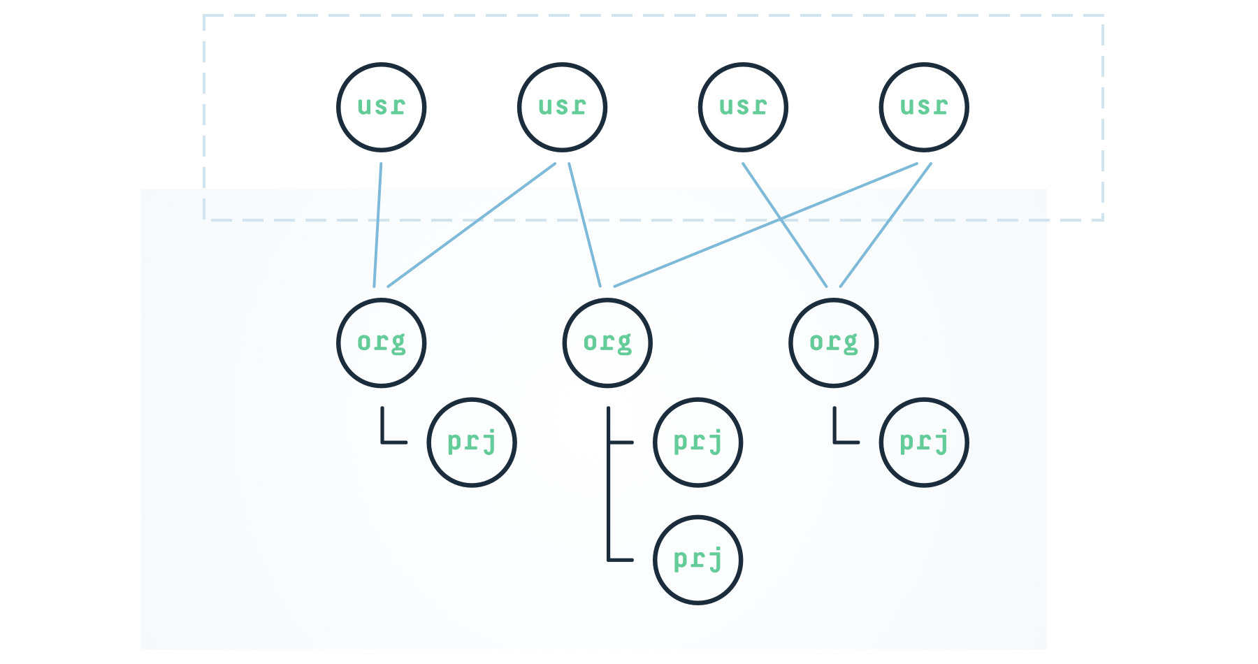
Glesys accounts manage organizations, collaborators, projects, and security, with users controlling authentication, billing, and access while organizations structure resources and permissions.
The control panel lets you manage organizations, configure company details, set billing methods, and assign collaborators while organizing projects efficiently overall.
Projects group related resources, with each organization managing project creation, settings, and identifiers via control panel or API endpoints for management.
# Release notes
***
Release notes document incremental improvements and major releases for the Glesys cloud platform.
You can subscribe to the RSS feed for release notes.
## Upcoming changes
## May 2025
# Regional availability
***
Glesys operates three data centers across three regions and also has a presence in three partner data centers in three additional regions.
{% tabs %}
{% tab title="Glesys data centers" %}
The following table displays each Glesys data center, its region, and its API/CLI slug:
| Data center | Region | Slug |
| ----------- | ------------------ | ------- |
| FBG1 | Falkenberg, Sweden | dc-fbg1 |
| STO1 | Stockholm, Sweden | dc-sto1 |
| OUL1 | Oulu, Finland | dc-oul1 |
| POR1 | Pori, Finland | dc-por1 |
| TAM1 | Tampere, Finland | dc-tam1 |
You can view the status of Glesys data centers on the [Glesys status page](https://status.glesys.com/).
{% endtab %}
{% tab title="Partner data centers" %}
The table below lists each partner data center along with its region:
| Data center | Region | Slug |
| ----------- | ---------------------- | ------- |
| AMS1 | Amsterdam, Netherlands | dc-ams1 |
| LON1 | London, United Kingdom | dc-lon1 |
| OSL1 | Oslo, Norway | dc-osl1 |
You can view the status of Glesys data centers on the [Glesys status page](https://status.glesys.com/).
{% endtab %}
{% endtabs %}
### Products
The table below summarizes our product availability, using the following keys:
* :green\_circle: **Full availability.** All customers can create this resource in this data center.
* :orange\_circle: **Limited availability**. There may be limited capacity in this data center, or the product may be in an earlier phase of the product lifecycle.
* :blue\_circle: **Future availability**. We intend to offer the product in this data center in the future, but we don’t currently.
* :red\_circle: **No availability**.
| Product | FBG1 | STO1 | OUL1 | AMS1 | LON1 | OSL1 |
| ---------------------------------- | --------------- | --------------- | --------------- | --------------- | --------------- | ---------------- |
|
| :green\_circle: | :green\_circle: | :green\_circle: | :green\_circle: | :green\_circle: | :green\_circle: |
| VMware Cloud Director as a Service | :green\_circle: | :green\_circle: | :green\_circle: | :red\_circle: | :red\_circle: | :red\_circle: |
| Dedicated Server | :green\_circle: | :green\_circle: | :green\_circle: | :red\_circle: | :red\_circle: | :orange\_circle: |
| Object Storage | :green\_circle: | :green\_circle: | :red\_circle: | :red\_circle: | :red\_circle: | :red\_circle: |
| Colocation | :green\_circle: | :green\_circle: | :green\_circle: | :red\_circle: | :red\_circle: | :red\_circle: |
| Remote Hands | :green\_circle: | :green\_circle: | :green\_circle: | :red\_circle: | :red\_circle: | :red\_circle: |
| FortiGate Firewall as a Service | :green\_circle: | :green\_circle: | :green\_circle: | :red\_circle: | :red\_circle: | :red\_circle: |
| Load Balancer | :green\_circle: | :green\_circle: | :red\_circle: | :red\_circle: | :red\_circle: | :red\_circle: |
# Support plans
***
# Service Level Agreements
Version 2024.01.01
***
The Service Level Agreements (SLAs) establish expectations between Glesys and the Customer. Both parties negotiate and agree on the services, performance targets, and scope. [Learn more](https://glesys.com/wp-content/uploads/2025/12/SLAs_en_updated-2024.01.01.pdf)
We offer three service levels: **SLA Basic**, **SLA Bronze**, and **SLA Gold**.
The agreements cover six definitions:
* Downtime
* Comprehensive Error
* Response Time
* Service Time
* Permissible Service Interruption
* Availability
If service levels are unmet, Glesys compensates customers with liquidated damages calculated as a percentage of the affected Service's monthly fee.
# Control panel
It's often sufficient to have a single Glesys account. One account can contain many organizations. Each account, in turn, can have several collaborators, projects, invoice settings, etc.
***
## Your personal user account
Glesys Cloud is built around you and your personal user account. On your account, you add payment cards, change your password, and create API keys.
You can also enable two-factor authentication (2FA) on your account. We support both Google Authenticator and YubiKey.
As a user, you can own or belong to one or several organizations.
### Two-factor authentication
You set up 2FA in the [settings](https://cloud.glesys.com/#/settings) for your user account. You find the settings by clicking on your name in the upper-right corner. When the menu opens, click on your name again.
By requiring something beyond just a password at login, security is significantly increased. By default, all accounts are protected with two‑step verification via email. For users who wish, the extra verification step can be linked to a physical device they possess—such as a hardware security key or a smartphone.
#### YubiKey
A YubiKey is an authentication device that generates a one‑time password. Our YubiKey model plugs into a computer’s USB port, and pressing the key’s gold disc produces the password. At present, U2F keys are not supported.
Key advantages:
* Works out of the box with no configuration required
* Compatible with Windows, macOS, Linux, iPad, Firefox, Chrome, and more
* Operates as a USB keyboard, needing no client software or drivers
* Waterproof, tamper‑proof, and contains no battery or display
* Simple, cost‑effective, and easy to carry on a keyring
* Currently supported by many cloud services
#### Authenticator apps
When it comes to using an app on your smartphone, there are many solutions that all rely on the same standard. Examples include 1Password, Google Authenticator, iCloud Keychain, or Authy. The app generates a one‑time code that you must enter when logging into the Glesys control panel.
## Organizations
All contact information and invoices are gathered under organizations, and the organization is always listed as the recipient on the invoices; of course, an organization can also represent a private individual.
An organization always has at least one owner.
## Owners and collaborators
As the owner of an organization, you can invite other users to your organization. When a user accepts your invitation, they become a collaborator in the organization. You can easily define what permissions a collaborator should have—or whether they should also be an owner.
For example, you can invite a consultant who only needs access to the servers in a specific project, or the finance department, which only needs to view invoices but not administer servers. As the organization’s owner, you stay in control.
Owners always have full rights and access to the entire organization, including the ability to create new projects.
## Projects
All Glesys services are grouped under what we call [Projects](/platform/control-panel/projects). Within a project, you’ll find servers, domains, load balancers, and other services.
For example, you might create one project for a production environment and another for a lab environment, or separate projects for different customers.
As an organization owner, you can create multiple projects under a single organization.
# Organizations
Each cloud account can contain several organizations.
***
## Managing organizations using the control panel
The account's organizations are shown in the sidebar to the left.
To create a new organization, click on the plus sign.
When you click on an organization, you'll be shown an overview. Among other things, you can see its collaborators. At the bottom of the menu, to the left of the current organization, you find the organization menu. Here you can set up collaborators, invoice settings, etc. The name of the organization in the screenshot below is Glesys Lab.
### Company information
Under the **Settings** menu in the organization menu, you set up your company information, such as company name, business identification number, address, email, and phone number. This is the first thing you need to do for a new organization.
### Payments
Under the **Billing** menu, you can choose whether to pay by credit card or by invoice. Note that you cannot create any services until you have selected a payment method and provided all the necessary information for that method.
If you choose to pay by invoice, save the settings, and then go back to the **Billing** menu. You can then choose if you want to receive the invoice by email or snail mail.
To pay by credit card, choose *Credit card* under **Method of Payment**. Fill in the information for the organization, and click **Continue** down to the right.
A new page will open. Here, you enter your credit card number, expiry date, and security code (CVC).
Once you've filled in the details, click **Accept 1 EUR**. Now, you might need to identify yourself using an electronic identification method. One euro will be charged to your credit card to verify the details. The money will be refunded within a few days.
When everything is set up correctly, the image below will be shown to confirm that the credit card has been added. Future invoices will, from now on, be paid automatically by credit card.
#### Replace an expired card
To replace an expired card, select **Billing** in the organization menu. Then, click **Select Payment Method**.
Click the **Continue** button at the bottom right—just like when you added the credit card for the first time. The page with the credit card details opens, and you can enter the new card information.
Once the details are filled out, click **Accept 1 EUR** to verify the test amount. You might need to verify your identity using an electronic identification method.
When everything is completed, you can verify it by clicking **Billing** again in the organization menu. The last four digits of the new card should now be displayed.
## Managing organizations using the API
Organizations can be managed using the [customer module](https://github.com/GleSYS/API-docs/wiki/API-Documentation#customer-module) in the [API](/platform/control-panel/api). To set up payment options, billing, and company information, use the [customer/settings](https://github.com/GleSYS/API-docs/wiki/API-Documentation#customersettings) endpoint.
# Billing
Explanation of billing processes, available payment methods, contract commitments, and how to properly terminate services.
Payment options
We support payments via bankgiro, domestic and international transfers, credit cards, and PayPal, providing multiple secure options for settling invoices efficiently.
Service terms vary: cloud uses pay-as-you-go with minimal commitment, while dedicated servers, connectivity, and colocation follow monthly billing with binding periods.
Our billing uses advance monthly charges with fair adjustments for upgrades, downgrades, or deletions, ensuring transparent costs and clear invoice breakdowns for all services.
Payment reminders indicate unregistered invoices, may include fees, and do not cancel services, as formal termination must follow proper cancellation procedures.
Service termination requires notice; non-payment doesn’t cancel services. Delete cloud servers in the control panel, while monthly services require written notice.
The Glesys Provider lets you manage supported resources once configured with valid credentials, with detailed guidance available through the resource navigation menu.
# Payment options
### Bankgiro
**Bankgiro:** 5296-1257
### Bank transfer (domestic)
**Bank:** Falkenbergs Sparbank\
**BIC (SWIFT):** SWEDSESS\
**IBAN:** SE0980000806061831600760
### International transfers (payment in EUR
**Bank:** Falkenbergs Sparbank\
**BIC (SWIFT):** SWEDSESS\
**IBAN:** SE9680000806063376726356
### Card payment (VISA or Master)
Available through our [control panel](https://cloud.glesys.com/login).
### Paypal
Available through our [control panel](https://cloud.glesys.com/login).
# Contract terms
Our services have varying contract terms depending on the service type. Understanding these terms helps clarify your commitments and billing.
### Cloud services
Billing follows a pay-as-you-go model with no fixed contract period by default, a minimum commitment of just one hour, and you only pay for the capacity you use.
### Monthly billed (binding) services
The following services are billed monthly and may include a binding contract period:
* Dedicated servers
* Internet connectivity
* Colocation
Unless otherwise agreed, these services renew monthly with a one-month binding period. Any different contract term will be clearly specified in the quotation or agreement before signing.
For complete details on all terms and conditions, please refer to our [general terms & conditions](https://glesys.com/terms-policies/general-terms-and-conditions).
# Understanding your invoice
Our billing system is designed to be flexible and transparent, especially for virtual servers that may change over time. This guide explains how our billing works, how changes are calculated, and what to expect on your invoice.
### How billing works
We use a hybrid model:
**Advance billing:** You pay in advance for the coming month, based on each server’s configuration at the time of invoicing.
**Adjustments in arrears:** Any changes made after billing (upgrades, downgrades, new or deleted servers) are calculated and adjusted on your next invoice.
This ensures you're always paying fairly for the exact resources you use.
### What you’ll see on your invoice
Each invoice has two key sections:
#### **New billing period**
* Cost for all active servers and services for the coming month.
* Billed in advance.
* Example: If you’re billed monthly, you pay one month in advance for all services.
#### **Changes since last invoice**
* Adjustments for any changes during the previous month.
* Examples:
* **Added server mid-month:** pay only for the days it was active.
* **Deleted server mid-month:** receive a credit for unused time.
* **Upgrades/downgrades:** billed or credited for the difference for the rest of the prepaid period.
### Example: how changes are billed
Here’s how adjustments work in practice.
#### Scenario
* A server costs 100 SEK/month when created.
* Billing is monthly.
* The customer adds, upgrades, downgrades, and deletes the server at various times.
#### February Invoice (issued February 1st)
**Includes:**
* New server created mid-January → 50 SEK (half month).
* February in advance → 100 SEK.
* **Total:** 150 SEK.
#### March Invoice (issued March 1st)
**Includes:**
* No changes in February → no adjustments.
* March in advance → 100 SEK.
* **Total:** 100 SEK.
During March, the customer makes three changes:
| | | |
| ---------- | ------------------- | -------------- |
| **Action** | **Timing in month** | **Adjustment** |
| Upgrade | 1/4 into March | +30 SEK |
| Downgrade | 2/4 into March | -40 SEK |
| Deletion | 3/4 into March | -15 SEK |
#### April invoice (issued April 1st)
**Includes:**
* Adjustments for March:
* +30 SEK (upgrade)
* -40 SEK (downgrade)
* -15 SEK (deletion)
* **Total adjustment:** -25 SEK (credit)
* No advance charges (server was deleted in March).
* **Total:** -25 SEK (credit balance).
### Checking your billing in the control panel
In the control panel, you can view all issued invoices, see an estimate of your next invoice based on current usage and configuration, and track pending changes that will be billed or credited, with all estimates updating automatically as you make changes to servers or services.
### Need Help?
If you have questions about your invoice or need help understanding charges, contact our support team. We’re happy to assist.
# Payment reminder
Information about payment reminders, fees for overdue invoices, and the proper process for termination.
If you have received a payment reminder from us, it means that we have not yet recorded a payment for one or more of your invoices. If you made a payment via Bankgiro or Plusgiro shortly before the reminder date, it may not yet have been registered. It typically takes 2–3 days for us to receive and process your transaction through Bankgiro or Plusgiro.
### Reminder fee
A reminder fee of SEK 45 will be added to your next invoice. If multiple reminder fees appear on your invoice, this may be due to several reminders being sent. This can occur, for example, if you have a billing interval of three months and we have had to remind you more than once.
### Non-payment does not constitute service termination
Please remember that simply not paying your invoice does not cancel your service. To terminate, you must follow the proper cancellation procedure. [Read more here](#termination).
For complete details on all terms and conditions, please refer to our [general terms & conditions](https://glesys.com/terms-policies/general-terms-and-conditions).
# Termination
Instructions for terminating cloud and monthly billed services, including termination of services with binding periods.
### Important notice: non-payment does not constitute service termination
Please be aware that non-payment of invoices does not automatically cancel your service. To properly terminate your service, you must follow the official cancellation procedure outlined below.
### Terminating cloud services
To terminate a cloud server, simply delete it via the control panel. If you have prepaid, a credit invoice or refund will be issued automatically for any unused time.
### Terminating monthly billed services
For services billed monthly, termination takes effect at the end of the current billing period. To terminate these services, you must submit a written notice by one of the following methods:
* **By email:** Send your termination request to . The request must be sent from the email address associated with your Glesys account for verification purposes.
* **By regular mail:**\
\
Glesys AB\
Box 134\
311 22 Falkenberg\
Sweden
### Terminating services with binding periods
If you have a pending binding period, the service cannot be terminated before the end of that contractual term. Once the binding period has expired, termination must be done in the same way as for monthly billed services by submitting a written notice either by email or regular mail as outlined above.
For complete details on all terms and conditions, please refer to our [general terms & conditions](https://glesys.com/terms-policies/general-terms-and-conditions).
# Projects
Projects are used to group servers, IP addresses, storage, and other resources that belongs together.
***
## Managing projects using the control panel
Each organization must have at least one project. If you haven’t already created a project, a green button with the text **Create your first project** will appear at the top of the left-hand menu.
The current project is always displayed at the top of the left-hand menu. By clicking the three dots next to the project name, you can change the project's name and color or request its removal.
If you click on the project name or the downward arrow, you can create new projects.
### The project's ID number
The project's ID number is used for many purposes in Glesys, such as a prefix for usernames in various services like the VPN service. The project's ID number is also used for API calls.
You find the project's ID number in the browser's URL field. For example, the URL might look like this: `https://cloud.glesys.com/#/12345?project=cl43212`. Here, `cl43212` is the project's ID number. The number `12345` is the organization's ID number.
## Managing projects using the API
You can manage your projects using the [API](/platform/control-panel/api). To list your current projects, use the [customer/listprojects](https://github.com/GleSYS/API-docs/wiki/API-Documentation#customerlistprojects) endpoint. To create a new project, use the [customer/createproject](https://github.com/GleSYS/API-docs/wiki/API-Documentation#customercreateproject) endpoint.
To edit a project, such as its color, use the [project/edit](https://github.com/GleSYS/API-docs/wiki/API-Documentation#projectedit) endpoint. To rename a project, use the [project/rename](https://github.com/GleSYS/API-docs/wiki/API-Documentation#projectrename) endpoint. To delete a project, use the [project/delete](https://github.com/GleSYS/API-docs/wiki/API-Documentation#projectdelete) endpoint.
# Collaborators
You can invite collaborators to your organization and assign them to different projects.
***
## Manage collaborators using the control panel
### Invite new collaborators
You create new collaborators by inviting them via email. Start by clicking on **Collaborators** in the organization's settings at the bottom of the left-hand side menu. Then click the green **Invite** button in the upper-right corner.
Enter the collaborator's email address in the provided field and click **Send**.
### Accept an invite
{% tabs %}
{% tab title="Without a prior Glesys Cloud account" %}
The collaborator will receive an invitation via email. Note that the person must accept the invitation before becoming a member of the organization.
When the collaborator clicks the invitation link in the email, they will be prompted to log in to their Glesys Cloud account. If the collaborator does not already have an account, they have to create one first using the same email address to which the invite was sent. Creating a Glesys Cloud account is free.
After the collaborator has created an account and logged in, they'll find the invite by clicking on the profile picture, then **Invites**. This will display a list of all pending invites.
Now the collaborator clicks **Accept** to accept the invite and become a member of the organization.
{% endtab %}
{% tab title="With a prior Glesys Cloud account" %}
If the invite is sent to an email address with a prior Glesys Cloud account, a dot will appear next to the profile picture in the control panel for that person's account. Click the profile picture, and a dot next to **Invites** will be visible. Clicking **Invites** will display a list of all pending invites.
Now the collaborator clicks **Accept** to accept the invite and become a member of the organization.
{% endtab %}
{% endtabs %}
### Permissions for collaborators
When a collaborator is created, they have no permissions in the organization. Permissions are assigned to collaborators for each project within the organization. Alternatively, a collaborator can be given the role of *Owner* instead of *Collaborator*. As an Owner, they gain access to the entire organization and can modify all settings, including billing settings and inviting other collaborators.
To assign permissions to a collaborator, go to **Collaborators** in the organization menu (at the bottom of the left-hand side menu). Then click on the collaborator you want to assign permissions to.
In the example below, the user named *Colleague* has the role of *Collaborator* and full permissions for the project *Lab1*. This means they can create, modify, and delete all types of resources within the *Lab1* project. However, they have no permissions for the *Lab2* project.
### Delete a collaborator
To delete a collaborator, go to **Collaborators** in the organization menu and select the collaborator you want to delete. Then, click **Actions** and choose **Delete**.
## Manage collaborators using the API
To list the current collaborators using the [API](/platform/control-panel/api), use the [customer/listcollaborators](https://github.com/GleSYS/API-docs/wiki/API-Documentation#customerlistcollaborators) endpoint. To set permissions for a collaborator, use the [customer/editcollaborator](https://github.com/GleSYS/API-docs/wiki/API-Documentation#customereditcollaborator) endpoint. To remove a collaborator, use the [customer/removecollaborator](https://github.com/GleSYS/API-docs/wiki/API-Documentation#customerremovecollaborator) endpoint.
To invite a new collaborator, use the `invite/create` endpoint.
## Manage invites using the API
To list all pending invites, use the [user/listinvites](https://github.com/GleSYS/API-docs/wiki/API-Documentation#userlistinvites) endpoint.
# API
Using the API, you can manage everything—from organizations and projects to servers, IP addresses, and more—entirely programmatically.
***
It is possible to control the features of the control panel via an API, enabling automation of many tasks. For example, you can run a script on a VM that uses the API to automatically adjust the number of CPU cores as the load fluctuates. A sample script for this purpose is available on [GitHub](https://github.com/glesys/api-docs/tree/master/BASH/LocalCPUCoresUpgradeDowngrade).
This section serves as a getting-started guide for the Glesys API. The complete API documentation can be found on the [Glesys GitHub page](https://github.com/glesys/api-docs/wiki).
## Create keys
There are two types of API keys: permanent and temporary.
*Permanent keys* are created in advance and can be used from predefined IP addresses. You also specify the key's permissions before it can be used.
*Temporary keys* are retrieved by logging in to the API using a username and password. This is the same username and password you use to log in to the control panel in Glesys Cloud. Upon logging in, you receive a list of organizations and projects that the user has access to. These are the same organizations and projects you have granted the user access to under Permissions for collaborator in the control panel. You use these projects or organizations as the username when making API calls. The password is the API key you received when you logged in with your username and password.
{% tabs %}
{% tab title="Permanent keys" %}
You find the page for permanent API keys under your user profile in the control panel. Click on the user icon in the top-right corner and select **Control API access**.
In the dialog box that appears, click the **Create** button. In the next dialog box, we enter a name for the key and specify which project it should have access to. In the example image below, we name the key *my-test-key* and grant it access to the project *Lab1*. Click **Create** to generate the key.
By default, new keys have no access from any IP addresses and no permissions to do anything. Start by granting *access* to the key from an IP address. Click **Access** in the **Actions** menu for the key.
Here, enter the IP addresses that should be able to use the API key. It is possible to specify both individual addresses and entire networks. The IP addresses and networks are separated by commas. Hostnames can also be specified. Additionally, access can be granted to all IP addresses by using the network 0.0.0.0/0. However, this should be avoided.
In the example below, only the IP addresses 203.0.113.2, 203.0.113.11, and the network 192.0.2.0/24 can use the key. Click **Add** to save and add the IP addresses.
After clicking **Add**, the keys are displayed in the same dialog box under *Hosts with access*. If everything looks correct, close the dialog box by clicking **Close**.
In the overview, it now shows how many hosts have access to the key.
Next, you need to grant the key *permissions* to perform various actions on different types of resources. To do this, click **Permissions** in the **Actions** menu for the key.
The permissions for keys are divided into modules. You can choose to grant the key permission to use all modules or restrict it to only the modules that are needed. It is more secure to only grant keys the permissions they genuinely require. Therefore, click **Show modules** to assign permissions to specific modules.
For each module listed, you can either grant full permissions to that module or specify which functions within the module the key should have permission to use. To display a module's functions, click **Show functions** next to the module.
In the example below, we have granted the key full permissions for the *Server* module, meaning the key can perform all functions for servers in the project where the key was created. For the *IP* module, the key has only specific permissions. Note that the image below is cropped and shows only a portion of the available modules.
Click **Save** at the bottom of the dialog box to save the key's permissions.
### Test the permanent key
You have now created the key, assigned permissions to certain modules, and granted access to the key from specific IP addresses. Now it’s time to test the key.
To test the key, you first need to copy the key's password. In the key's overview, click the icon to copy the key's password. The username for the key is the project; in this example, it is *cl43212*.
Now, try making an API call using cURL. Keep in mind that the call must be made from an IP address that you have added to the access list.
The URL for the API is `https://api.glesys.com`. The function we are testing here is `/server/list`. Note that the key must have permission to use `/server/list`. We use *basic auth* for authentication. For security purposes, we disable the shell history first.
{% code title="Multiple commands" %}
```
set +o history
curl -X POST https://api.glesys.com/server/list -u cl43212:kucxxxyyyzzz
```
{% endcode %}
The response from the API will look like the example below (note that this is just a brief excerpt of the full output).
{% code title="API response" %}
```xml
2002023-09-21T15:38:35+02:00OKkvm3652342cl43212testvm5FalkenbergKVM1204830100Ubuntu 22.04 LTS (Jammy Jellyfish)
```
{% endcode %}
Now we know that the key works, and we can re-enable the shell history:
{% code title="Command" %}
```terminal
set -o history
```
{% endcode %}
{% endtab %}
{% tab title="Temporary keys" %}
Temporary keys are created by logging into the API using the same username and password you use to log in to the Glesys Cloud control panel. The key created, therefore, has the same permissions as the user logging in to create it. A temporary key expires after six hours of inactivity.
To create a temporary key, start by logging into the API using the `/user/login` function. As parameters, you must provide the account's username and password. Since you will be entering your account password, start by disabling the shell history. Afterward, you can re-enable the history. Enclose the URL in quotation marks because it contains special characters that the shell would otherwise interpret.
{% code title="Multiple commands" %}
```terminal
set +o history
curl -X POST "https://api.glesys.com/user/login?username=colleague@example.com&password=xxx"
```
{% endcode %}
The response includes information about what the user has access to, as well as the key to be used as the password. It might look like the example below (this is just a brief excerpt from a much longer response):
{% code title="API response" %}
```xml
colleague@example.comxxx-yyy-zzz-123cl43212FullAccess123456ReadOnly
```
{% endcode %}
Here, you can see that the user has full permissions for the project *cl43212*, but only read permissions for the organization *123456*.
In the response, you also received the API key, *xxx-yyy-zzz-123*.
### Testing the temporary key
You can now use the project, *cl43212*, as the username and the API key, *xxx-yyy-zzz-123*, as the password to make API calls. It is also possible to use the organization number as the username, but in this case, we only have read permissions for the organization. Additionally, the control panel username can be used. Depending on what you use as the username (project, organization, or Cloud account), you gain access to different features.
For example, using the Cloud account as the username provides access to personal account details. Using the project as the username grants access to project-based functions, such as creating, starting, and stopping VMs. Using the organization as the username allows access to organization-wide features, such as invoice management and similar tasks.
Since this user has full access to the project *cl43212*, we will use it as the username and list all servers. Provide the username and password as *basic auth*:
{% code title="Command" %}
```terminal
curl -X POST https://api.glesys.com/server/list -u cl43212:xxx-yyy-zzz-123
```
{% endcode %}
The response you receive looks something like the example below (this is just a brief excerpt from a much longer response):
{% code title="API response" %}
```xml
2002023-09-21T20:06:56+02:00OKkvm3652342cl43212testvm5FalkenbergKVM1204830
```
{% endcode %}
This confirms that the temporary key works.
{% endtab %}
{% endtabs %}
## Some examples
Regardless of the type of key you use, the API works the same way and provides the same functions.
### JSON as response type
By default, the API responds with an XML document. If you want the response as a JSON object instead, you need to specify this to the API by including a header in the request. To format the JSON data, you can pipe it to `jq` (omit `jq` to get the raw JSON data):
{% code title="Command" %}
```terminal
curl -X POST https://api.glesys.com/server/list -u cl43212:kucxxxyyyzzz \
--header "Accept: application/json" | jq
```
{% endcode %}
The response you receive looks something like the example below (this is just a brief excerpt from a much longer response):
{% code title="API response" %}
```json
{
"response": {
"status": {
"code": 200,
"timestamp": "2023-09-21T19:14:24+02:00",
"text": "OK"
},
"servers": [
{
"serverid": "kvm3652342",
"projectkey": "cl43212",
"hostname": "testvm5",
"datacenter": "Falkenberg",
"platform": "KVM",
"description": null,
"cpucores": 1,
"memorysize": 2048,
"disksize": 30,
"transfer": null,
"bandwidth": 100,
"templatename": "Ubuntu 22.04 LTS (Jammy Jellyfish)",
"initialtemplate": {
"id": "f4521a83-e541-47b2-bc09-94161fe8b40d",
"name": "Ubuntu 22.04 LTS (Jammy Jellyfish)",
```
{% endcode %}
### Update a PTR record
For functions that require arguments, you specify these as parameters in standard URL format. For example, to update the PTR record for an IP address, you provide the IP address and the fully qualified domain name (FQDN) as parameters to the `/ip/setptr` function:
{% code title="Multiple commands" %}
```terminal
set +o history
curl -X POST \
"https://api.glesys.com/ip/setptr?ipaddress=203.0.113.121&data=testvm5.example.com." \
-u cl43212:xxx-yyy-zzz-123
```
{% endcode %}
The response indicates whether the update was successful. The output below is just a brief excerpt.
{% code title="API response" %}
```xml
2002023-09-21T20:24:49+02:00PTR updated.
```
{% endcode %}
### Example with Python
To list all servers using Python, you can create a short script like the one below. We name it `glesys-api.py`.
{% code title="glesys-api.py" %}
```python
import requests
import json
url = 'https://api.glesys.com'
endpoint = '/server/list'
username = 'cl43212'
password = 'kucxxxyyyzzz'
headers = {
'Accept': 'application/json'
}
response = requests.post(url + endpoint, headers=headers, auth=(username, password))
print(json.dumps(response.json(), indent=2))
```
{% endcode %}
Execute the script:
{% code title="Command" %}
```terminal
python3 glesys-api.py
```
{% endcode %}
An excerpt from the output is shown here:
{% code title="Output" %}
```json
{
"response": {
"status": {
"code": 200,
"timestamp": "2023-09-22T08:40:35+02:00",
"text": "OK"
},
"servers": [
{
"serverid": "kvm3652342",
"projectkey": "cl43212",
"hostname": "testvm5",
"datacenter": "Falkenberg",
"platform": "KVM",
"description": null,
"cpucores": 1,
"memorysize": 2048,
"disksize": 30,
"transfer": null,
"bandwidth": 100,
```
{% endcode %}
## Viewing the built-in API documentation
It's possible to view the API documentation by making calls to the API. This way, you can drill down to the specific endpoint you need.
For example, by making a POST or GET request to you'll get a list of all available modules.
{% code title="Multiple command" %}
```
set +o history
curl -X POST "https://api.glesys.com/" -u cl43212:xxx-yyy-zzz-123
```
{% endcode %}
This will return a 404 error, but will print out a list of all available modules.
{% code title="API response" %}
```xml
4042025-09-11T08:20:57+02:00Unknown module. Please specify module (ex: api.glesys.com/module/)serveripdatabasedomainarchiveemailinvoicecountrycustomeraccountpaymentcardvpnloadbalanceruserapisshkeynetworkadapternetworkcircuitnetworkfilestorageprojectobjectstorageserverdiskprivatenetworkcl4321231704
```
{% endcode %}
You can now make another request to a module of interest, for example, the object storage module.
```
set +o history
curl -X POST "https://api.glesys.com/objectstorage/" -u cl43212:xxx-yyy-zzz-123
```
This will now result in another 404 error, but this time it will return all the information about the module's available functions and their required and optional arguments. The example below is just a short snippet of a much longer output.
{% code title="API response" %}
```xml
4042025-09-11T08:31:15+02:00Unknown function. Please specify function (ex: api.glesys.com/module/functionManage your Object Storage InstancestruetruefalsetruefalsefalseinstancedetailsGet detailed information of an Object Storage Instance such as datacenter, descriptions and associated credentials.11instanceidlistinstancesGet a list of Object Storage Instances for a project11projectkeycreateinstanceCreate a new Object Storage Instance. Your first credentials will be created automatically1projectkeydatacenterdescriptioncreateinitialbucket
```
{% endcode %}
# Real-world use cases
There are plenty of use cases for Glesys API.
***
On this page, we have gathered some real-world use cases of the Glesys API.
There are lots of operations that can be automated using the API, everything from acquiring an SSL certificate from Let's Encrypt to automatically expanding the memory of a virtual machine.
Let's Encrypt DNS-01 challenge using Glesys API and Dehydrated
By using the Glesys API and a small program called Dehydrated, it's possible to acquire SSL certificates using Let's Encrypt using a DNS challenge instead of a web server.
# Let's Encrypt DNS-01 challenge using Glesys API and Dehydrated
By using the Glesys API and a small program called Dehydrated, it's possible to acquire SSL certificates using Let's Encrypt using a DNS challenge instead of a web server.
***
Let’s Encrypt has released a type of challenge to verify that you are truly the owner of the domain for which you have created a certificate. This challenge does not require you to use a web server for verification; instead, it is entirely based on having access to create DNS records for the domain.
This guide shows how you can use the GleSYS API for this purpose.
## Setting up Dehydrated and issuing a certificate
You will need to install cURL and XMLStarlet if you don’t already have these packages installed.
{% tabs %}
{% tab title="Debian / Ubuntu" %}
For Debian and Ubuntu, use the following command to install the packages:
{% code title="Command" %}
```
sudo apt-get install curl xmlstarlet
```
{% endcode %}
{% endtab %}
{% tab title="CentOS / AlmaLinux" %}
For CentOS and AlmaLinux, use the following command (requires EPEL):
{% code title="Command" %}
```
sudo yum install curl xmlstarlet
```
{% endcode %}
For more information about EPEL, see the [EPEL Wiki](https://fedoraproject.org/wiki/EPEL).
{% endtab %}
{% endtabs %}
{% hint style="warning" %}
All commands you are going to run from this point must be executed as root. To avoid having to type `sudo` for every command, switch to a root login shell using `sudo -i`. All commands executed after this command will then be executed as root, until you run `exit`.
{% endhint %}
Next, enter the working directory `/etc/ssl/private`.
{% code title="Command" %}
```
cd /etc/ssl/private/
```
{% endcode %}
If, for some reason, the directory does not exist, you create it using the following command.
{% code title="Command" %}
```
mkdir /etc/ssl/private && chmod 700 /etc/ssl/private
```
{% endcode %}
The next step is to create environment variables (envvars) that contain the API references. Log in to Glesys Cloud and click on your profile in the upper‑right corner. Choose **Control API access**, then click the green **Create** button. In the *Create API Key* window that opens, select the project for which the key should be created and give it a name. In this case, the description is set to *letsencrypt*.
In the image below, you can see that an API key with no permissions has been created with the ID `0JSmAiYu3l0ZGCNAOa15jWOP7OXKFIidk47RVElQ`. This key is unique to this example; the key that was generated for you will differ.
To specify which IP address or domain is allowed to use the API key, click **Actions** and then select **Access**.
When you click **Add**, the changes take effect immediately. Press **Close** when you’re done.
Next, we’ll grant the API key permission to edit domains. Click **Actions** and select **Permissions**.
In the *Permissions for API-key* window that opens, select **Allowed** for the **Domain** row. Finish by clicking **Save**.
Now it’s time to start using the API key you created, and you do that by running the commands:
{% code title="Multiple commands" %}
```
echo "export USER=CL12345" > /etc/ssl/private/.glesys-credentials
echo "export KEY=ABCDE12345" >> /etc/ssl/private/.glesys-credentials
```
{% endcode %}
* Replace `CL12345` with the identifier of the project for which you created the key.
* Replace `ABCDE12345` with the key you generated. In our example, it is `0JSmAiYu3l0ZGCNAOa15jWOP7OXKFIidk47RVElQ`.
Download Dehydrated together with the example configuration and our hook script from GitHub:
{% code title="Multiple commands" %}
```
wget https://raw.githubusercontent.com/lukas2511/dehydrated/master/dehydrated
wget https://raw.githubusercontent.com/glesys/api-docs/master/BASH/LetsencryptGlesysHook/glesys-dns-01-hook.sh
wget https://raw.githubusercontent.com/glesys/api-docs/master/BASH/LetsencryptGlesysHook/config
```
{% endcode %}
Edit the `config` file and enter the values as shown below (but make sure to use you're own email address). Be sure to remove the comment symbols (the `#` characters) at the beginning of each line. Also, delete the line `CONFIG_D=/etc/dehydrated/conf.d` from the file since this isn't used in this case. A complete and fully working `config` file is shown below.
{% code title="/etc/ssl/private/config" %}
```
BASEDIR=/etc/ssl/private
WELLKNOWN="${BASEDIR}/acme-challenges"
DOMAINS_TXT="${BASEDIR}/domains.txt"
CHALLENGETYPE="dns-01"
HOOK="${BASEDIR}/glesys-dns-01-hook.sh"
CONTACT_EMAIL=user@example.com
CHAIN="yes"
CA="https://acme-v02.api.letsencrypt.org/directory"
```
{% endcode %}
Dehydrated uses domains.txt by default to manage the domains for which it should create or update certificates. The syntax of the file looks like this:
{% code title="domains.txt syntax example" %}
```
example.net www.example.net
example.se dev.example.se
```
{% endcode %}
This will create two certificates. One certificate for `example.net` with the *alternative name* `www.example.net` and another certificate for `example.se` with the *alternative name* `dev.example.se`.
In our example, we want to add the domain `example.com`. With the following command, we write to `domains.txt`:
{% code title="Command" %}
```
echo "example.com www.example.com" > domains.txt
```
{% endcode %}
You also need to set permissions on the files you created so that they can only be accessed by the root user. You do this with the following command:
{% code title="Multiple commands" %}
```
chmod 700 glesys-dns-01-hook.sh dehydrated
chmod 600 domains.txt config .glesys-credentials
```
{% endcode %}
If this is the first time you use Dehydrated with Let's Encrypt on this server, you first need to accept Let's Encrypt's terms of service. You do this using the following command:
{% code title="Command" %}
```
./dehydrated --accept-terms --register
```
{% endcode %}
This will output something similar to this:
{% code title="Output" %}
```
# INFO: Using main config file /etc/ssl/private/config
+ Generating account key...
+ Registering account key with ACME server...
+ Fetching account URL...
+ Done!
```
{% endcode %}
Finally, we run Dehydrated with the `-c` flag to generate the certificates for our domain:
{% code title="Command" %}
```
./dehydrated -c
```
{% endcode %}
The output will look similar to this:
{% code title="Output" %}
```
# INFO: Using main config file /etc/ssl/private/config
+ Creating chain cache directory /etc/ssl/private/chains
Processing example.com with alternative names: www.example.com
+ Signing domains...
+ Creating new directory /etc/ssl/private/certs/example.com ...
+ Generating private key...
+ Generating signing request...
+ Requesting challenge for example.com...
+ Requesting challenge for www.example.com...
+ Responding to challenge for example.com...
+ Challenge is valid!
+ Responding to challenge for www.example.com...
+ Challenge is valid!
+ Requesting certificate...
+ Checking certificate...
+ Done!
+ Creating fullchain.pem...
+ Done!
```
{% endcode %}
It’s all done now, and you can find the certificates in the directory `/etc/ssl/private/certs/`.
## Apache usage example
To use the certificates with your Apache 2 web server, add the following to its configuration:
{% code title="Apache2 config example" %}
```
SSLEngine on
SSLCertificateFile /etc/ssl/private/certs/example.com/cert.pem
SSLCertificateKeyFile /etc/ssl/private/certs/example.com/privkey.pem
SSLCertificateChainFile /etc/ssl/private/certs/example.com/chain.pem
```
{% endcode %}
## Automatically renew the certificate
A free SSL certificate from Let’s Encrypt is only valid for 90 days. To auto‑renew the certificate at 00:00 (midnight) every Saturday, you can use the following cron job (edit the crontab using `crontab -e`):
{% code title="crontab" %}
```
00 00 * * 06 /etc/ssl/private/dehydrated -c &>/dev/null
```
{% endcode %}
# Resize a VM when running out of memory
Using the Glesys API you can automatically resize a VM when it starts running low on memory.
***
The Glesys API can be used for many things, including upgrading the memory of a virtual server.
These scripts are ideally run from crontab every minute (adjust the scripts as needed). With a little extension, it’s easy to implement multi‑step upgrades and downgrades, send email notifications to the sysadmin on changes, upgrade the number of CPU cores, and so on.
If you modify these scripts or create completely different solutions, feel free to submit them to us so we can showcase them. **Well‑crafted scripts are rewarded with nice discounts!**
More information about the Glesys API can be found on [GitHub](https://github.com/glesys/api-docs/wiki).
## Increase the memory using Bash
Below, we show you how to create a script that checks how much memory is being used on the virtual server. When usage reaches 90%, the memory is upgraded to 4096 MB. If you schedule this as a cron job, you’ll get an automatic memory increase on your server whenever the memory limit is reached.
{% code title="/root/adjust-memory.sh" %}
```bash
#!/bin/bash
TOTAL=`cat /proc/meminfo |grep "MemTotal" |awk {'print $2'}`
FREE=`cat /proc/meminfo |grep -E "MemFree|Cached"| awk '{s+=$2} END {print s}'`
USAGE=$((100-FREE*100/TOTAL));
if [ $USAGE -gt 90 ]; then
/usr/bin/curl -X POST -d serverid=wps123456&memorysize=4096 -k --basic -u cl12345:API-KEY https://api.glesys.com/server/edit/
fi
```
{% endcode %}
## Increase the memory using Ruby
Below is a slightly more advanced script. When the usage goes above 90%, the memory is increased to 4096 MB. When the usage goes below 20%, the memory is decreased to 2048 MB. If you schedule this as a cron job, you’ll get automatic memory increase and decrease on your virtual server based on its usage.
{% code title="/root/adjust-memory.rb" %}
```ruby
require "net/http"
require "net/https"
require "uri"
def change_memory(memory, username, api_key, server_id)
params = { serverid: server_id, memorysize: memory }
uri = URI.parse("https://api.glesys.com/server/edit")
http = Net::HTTP.new(uri.host, uri.port)
http.use_ssl = true
request = Net::HTTP::Post.new(uri.request_uri)
request.basic_auth(username, api_key)
request.set_form_data(params)
response = http.request(request)
if response.code == "200"
puts "Memory changed to #{memory}"
end
end
def memory_usage
total_memory = `cat /proc/meminfo |grep -E "MemTotal"|awk {'print $2'}`.strip.to_f
free_memory = `cat /proc/meminfo |grep -E "MemFree|Cached"| awk '{s+=$2} END {print s}'`.strip.to_f
1 - (free_memory / total_memory)
end
if ARGV.size < 3
abort("required arguments: username apikey serverid")
end
username = ARGV[0]
api_key = ARGV[1]
server_id =ARGV[2]
memory_low=2048
memory_high=4096
if memory_usage > 0.9
puts "Increasing Memory"
change_memory(memory_high, username, api_key, server_id)
elsif memory_usage < 0.2
puts "Decreasing Memory"
change_memory(memory_low, username, api_key, server_id)
end
```
{% endcode %}
### Running the Ruby script in a cron job
Make the script executable with `chmod +x /root/adjust-memory.rb`. Then, add the script to the crontab using `crontab -e`. To run the script every minute, add the following line to the crontab:
{% code title="crontab" %}
```
* * * * * /root/adjust-memory.rb cl12345 API-KEY wps12345
```
{% endcode %}
# Load balancing and failover using the Glesys API
By using "DNS round robin" together with the Glesys API to add or remove servers, you achieve both load balancing and failover.
***
One of the simplest ways to load‑balance a web service is by using “DNS Round Robin.” In its most basic form, you have two servers, each with its own IP address. Then you create duplicate A records for the domain—one pointing to each server—so that traffic is distributed between the two servers. Below is an example of how to automatically remove and add those records.
## Automating failover
One of the issues with “DNS Round Robin” is that if one of the servers goes down, half of the visitors will be unable to reach the service.
This can, for example, be remedied using the Glesys API with a simple script shown below.
The Bash script runs on both servers. To check whether the other server is still functioning, its webpage is scanned for a specific text string. If that string is not found, the domain’s DNS records are changed so that both point to the working server. After that, the script continues to test whether the site is up. When the site comes back online, the DNS records are switched back so that both servers are used again.
To make this work, the script must be run on both servers, and the values for `THIS` and `THAT` need to be adjusted so that they reference each other.
{% hint style="danger" %}
Keep in mind that this is merely an illustrative example meant to spark ideas about how you can leverage DNS and the Glesys API to achieve powerful effects in a simple way. It is not intended to be used directly for load‑balancing production servers.
{% endhint %}
{% code title="failover.sh" %}
```bash
#!/bin/bash
#Note: This script is hard‑coded with record IDs. Check them with:
#/usr/bin/curl -X POST -d domain=example.com -k --basic -u cl12345:API-KEY https://api.glesys.com/domain/list_records
THIS="10.0.0.1"
THAT="10.0.0.2"
URL="http://$THAT/blog/testblog"
SEARCH="Some text on the site"
RECORD1="12345"
RECORD2="12346"
ACCOUNT="CL12345"
APIKEY="SECRET"
getStatus() { /usr/bin/wget -O - $URL 2> /dev/null | grep "$SEARCH" &>/dev/null; echo "$?"; }
setRecords(){
echo "setting records to $1 and $2";
/usr/bin/curl -X POST -d record_id=$RECORD1&data=$1 -k --basic -u $ACCOUNT:$APIKEY https://api.glesys.com/domain/update_record
/usr/bin/curl -X POST -d record_id=$RECORD2&data=$2 -k --basic -u $ACCOUNT:$APIKEY https://api.glesys.com/domain/update_record
}
while :
do
STATUS=$(getStatus)
if [ $STATUS -eq 1 ]; then
echo "Site is down!";
setRecords "$THIS" "$THIS"
while [ $STATUS -eq 1 ]; do
sleep 20
STATUS=$(getStatus)
echo "still down"
done
setRecords "$THIS" "$THAT"
fi
echo "Site is up!";
sleep 60
done
```
{% endcode %}
With the solution above, you can build a service with very high availability. For example, combine colocation in our Stockholm data center with a virtual server in Falkenberg, Amsterdam, Oslo, or London.
More information about the API is available on [GitHub](https://github.com/glesys/api-docs/wiki). There are also some more [examples on GitHub](https://github.com/glesys/api-docs/).
# RSS feed for invoices
Using the Glesys API, you can get an RSS feed for your invoices.
***
The Glesys API can be used for many purposes—for example, you can retrieve all invoices associated with the customer number linked to an account.
The PHP example below fetches a list of all invoices and formats them as an RSS feed. Deploy the script on your own server and create an API key that has permission to use the `invoice/list` function from your server’s IP address. Then add the feed to an RSS reader to receive notifications whenever a new invoice is sent to you.
More information about the API is available on [GitHub](https://github.com/glesys/api-docs).
{% code title="invoice-rss.php" %}
```php
GleSYS invoicesA list of all invoices for the account
http://www.glesys.se/
Mon, 19 Dec 2011 08:45:00 +00001800Invoice <?=$invoice['invoicenumber']?>
Due date:
Amount:
```
{% endcode %}
# Getting started with Terraform in Glesys Cloud
By using Terraform you can automate your Glesys Cloud using code.
***
The Glesys Provider for Terraform lets you manage resources in Glesys Cloud. Currently, it supports, among other things, **virtual machines** (KVM and VMware), **networking**, **load balancers**, and **object storage**.
On [GitHub](https://github.com/glesys), you can find our repository [`terraform-provider-glesys`](https://github.com/glesys/terraform-provider-glesys) along with the accompanying documentation.
## Prerequisites
You need permission to a Glesys Cloud account:
* Open a free account [here](https://cloud.glesys.com/#/signup)
* A project in the control panel (this is where your services reside)
* An API key. For this example, we use the following permissions for the **Server** module in the Glesys API:
* `create`
* `destroy`
* `details`
* `edit`
* `list`
## Example
Here is an example where we create a virtual server and then increase its disk size.
You can use this configuration by creating a file named `example.tf` in a directory and then running the following commands from that directory:
* Initialize a working directory for Terraform: `terraform init`
* Generate and display an execution plan: `terraform plan`
* Build your infrastructure: `terraform apply`
### Step 1: Install and configure Terraform
For Terraform to communicate with the Glesys API, you need to provide a project ID (clXXXXX) from Glesys Cloud as the username and an API key that can authenticate against that project.
In this example, we’ll export environment variables in a shell so you don’t have to specify them each time a command interacts with the Glesys API.
{% code title="Multiple commands" %}
```
export GLESYS_USERID=CL12345
export GLESYS_TOKEN=abc12345XYZ
```
{% endcode %}
Let's start by creating a directory for this example:
{% code title="Multiple commands" %}
```
mkdir glesys-terraform
cd glesys-terraform
```
{% endcode %}
In the directory, create a file called `example.tf`, which is used when you download the GleSYS Provider. Give the file the following content.
{% code title="example.tf" %}
```
terraform {
required_providers {
glesys = {
source = "glesys/glesys"
version = "~> 0.4.6" # Här kan du ändra om du vill köra en särskild version av providern.
}
}
}
```
{% endcode %}
By running the `terraform init` command, you initiate the download of the GleSYS Provider:
{% code title="Command" %}
```
terraform init
```
{% endcode %}
The output from the command will look similar to this:
{% code title="Output" %}
```
Initializing the backend...
Initializing provider plugins...
- Finding latest version of glesys/glesys...
- Installing glesys/glesys v0.4.6...
- Installed glesys/glesys v0.4.6 (self-signed, key ID 4B5E1D585D113D4D)
Partner and community providers are signed by their developers.
If you'd like to know more about provider signing, you can read about it here:
https://www.terraform.io/docs/cli/plugins/signing.html
Terraform has made some changes to the provider dependency selections recorded
in the .terraform.lock.hcl file. Review those changes and commit them to your
version control system if they represent changes you intended to make.
Terraform has been successfully initialized!
You may now begin working with Terraform. Try running "terraform plan" to see
any changes that are required for your infrastructure. All Terraform commands
should now work.
If you ever set or change modules or backend configuration for Terraform,
rerun this command to reinitialize your working directory. If you forget, other
commands will detect it and remind you to do so if necessary.
```
{% endcode %}
You are now ready to create resources in Glesys Cloud!
### Step 2: Create a virtual server
To create a virtual server, you need to add several parameters to the `example.tf` file. We recommend reading the documentation for [`glesys_server`](https://registry.terraform.io/providers/glesys/glesys/latest/docs/resources/server), where you can also see which parameters are required and which are optional.
If you want to spin up a virtual machine (KVM) running Debian 12 in the Stockholm data center and also create two users (*alice* and *bob*), the parameters would look like the example below. You can also clearly see how much resources have been allocated to the server. Add the following content to the previously created `example.tf` file:
{% code title="Additions to example.tf" %}
```
resource "glesys_server" "kvm" {
count = 1
datacenter = "Stockholm"
memory = 1024
storage = 20
cpu = 1
bandwidth = 100
hostname = "www1"
platform = "KVM"
template = "debian-12"
user {
username = "alice"
publickeys = [
"ssh-ed25519 AAAAC3NzaC1lZDI1NTE5AAAAINOCh8br7CwZDMGmINyJgBip943QXgkf7XdXrDMJf5Dl alice@example.com",
"ssh-ed25519 AAAAC3NzaC1lZDI1NTE5AAAAIOfN4dBsS2p1UX+DP6RicdxAYCCeRK8mzCldCS0W9A+5 alice@ws.example.com"
]
password = "hunter3!"
}
user {
username = "bob"
publickeys = ["ssh-ed25519 AAAAC3NzaC1lZDI1NTE5AAAAINOCh8br7CwZDMGmINyJgBip943QXgkf7XdXrDMJf5Dl bob@example.com"]
password = "hunter333!"
}
}
```
{% endcode %}
To create the virtual machine, you first let Terraform read the configuration file and show which changes need to be made to your infrastructure. You do this by running `terraform plan`.
Then we run the `terraform apply` command to build the infrastructure:
terraform apply

Terraform used the selected providers to generate the following execution plan. Resource actions are indicated with the following symbols:
  + create

Terraform will perform the following actions:

  # glesys_server.kvm[0] will be created
  + resource "glesys_server" "kvm" {
      + bandwidth    = 100
      + cpu          = 1
      + datacenter   = "Stockholm"
      + hostname     = "www1"
      + id           = (known after apply)
      + ipv4_address = (known after apply)
      + ipv6_address = (known after apply)
      + memory       = 1024
      + platform     = "KVM"
      + storage      = 20
      + template     = "debian-12"

      + user {
          + password   = "hunter3!"
          + publickeys = [
              + "ssh-ed25519 AAAAC3NzaC1lZDI1NTE5AAAAINOCh8br7CwZDMGmINyJgBip943QXgkf7XdXrDMJf5Dl alice@example.com",
              + "ssh-ed25519 AAAAC3NzaC1lZDI1NTE5AAAAIOfN4dBsS2p1UX+DP6RicdxAYCCeRK8mzCldCS0W9A+5 alice@ws.example.com",
            ]
          + username   = "alice"
        }
      + user {
          + password   = "hunter333!"
          + publickeys = [
              + "ssh-ed25519 AAAAC3NzaC1lZDI1NTE5AAAAINOCh8br7CwZDMGmINyJgBip943QXgkf7XdXrDMJf5Dl bob@example.com",
            ]
          + username   = "bob"
        }
    }

Plan: 1 to add, 0 to change, 0 to destroy.

Do you want to perform these actions?
  Terraform will perform the actions described above.
  Only 'yes' will be accepted to approve.

  Enter a value: yes

glesys_server.kvm[0]: Creating...
glesys_server.kvm[0]: Creation complete after 4s [id=kvm123456]
After a successful run, you can move on to the next step.
#### Show the current state
With the `terraform show` command you can view the final result of the run. Details such as IPv4/IPv6 addresses have now been returned from the API.
{% code title="Command" %}
```
terraform show
```
{% endcode %}
{% code title="Output" %}
```
resource "glesys_server" "kvm" {
bandwidth = 100
cpu = 1
datacenter = "Stockholm"
hostname = "www1"
id = "kvm123456"
ipv4_address = "46.246.39.1"
ipv6_address = "2a00:1a28:1410:5::1"
memory = 1024
platform = "KVM"
storage = 20
template = "debian-12"
user {
password = "hunter3!"
publickeys = [
"ssh-ed25519 AAAAC3NzaC1lZDI1NTE5AAAAINOCh8br7CwZDMGmINyJgBip943QXgkf7XdXrDMJf5Dl alice@example.com",
"ssh-ed25519 AAAAC3NzaC1lZDI1NTE5AAAAIOfN4dBsS2p1UX+DP6RicdxAYCCeRK8mzCldCS0W9A+5 alice@ws.example.com",
]
username = "alice"
}
user {
password = "hunter333!"
publickeys = [
"ssh-ed25519 AAAAC3NzaC1lZDI1NTE5AAAAINOCh8br7CwZDMGmINyJgBip943QXgkf7XdXrDMJf5Dl bob@example.com",
]
username = "bob"
}
}
```
{% endcode %}
### Step 3: Increase the disk size
To increase the virtual machine’s disk size, simply modify the value in `example.tf` and run `terraform apply` again. In this example, we have changed it from 20 to 30 GiB.
terraform apply
glesys_server.kvm[0]: Refreshing state... [id=kvm123456]

Terraform used the selected providers to generate the following execution plan. Resource actions are indicated with the following symbols:
  ~ update in-place

Terraform will perform the following actions:

  # glesys_server.kvm[0] will be updated in-place
  ~ resource "glesys_server" "kvm" {
        id           = "kvm123456"
      ~ storage      = 20 -> 30
        # (9 unchanged attributes hidden)

        # (2 unchanged blocks hidden)
    }

Plan: 0 to add, 1 to change, 0 to destroy.

Do you want to perform these actions?
  Terraform will perform the actions described above.
  Only 'yes' will be accepted to approve.

  Enter a value: yes

glesys_server.kvm[0]: Modifying... [id=kvm123456]
glesys_server.kvm[0]: Modifications complete after 1s [id=kvm123456]

Apply complete! Resources: 0 added, 1 changed, 0 destroyed.
## Contribute open-source code
Everyone is welcome to contribute to the project with new features, improvements, and bug fixes. Read more about how to get started [here](https://github.com/glesys/terraform-provider-glesys/blob/main/README.md).
## Further reading
* [An introduction to Glesys API](https://github.com/glesys/api-docs/wiki/Api-Introduction).
* [The complete API documentation](https://github.com/glesys/api-docs/wiki/API-Documentation).
# Status information
There are several places where Glesys publish status information.
***
At [www.glesys-status.com](https://www.glesys-status.com/), you can view current operational information. It is also possible to subscribe to operational updates via email and other channels such as Slack, Microsoft Teams, and Google Chat.
## Subscribe to status updates
To subscribe to operational updates from Glesys, click the **Subscribe** button and enter your email address. When you sign up, you can also choose to get notified through other channels, such as Slack.
## Manage your status subscription
You can later log in to the status page and update your preferences or end the subscription. To log in, click the **Subscribe** button again. Then, click **Already subscribed?**
## Status information in the control panel
Planned or ongoing service interruptions will also be displayed in the control panel's top-right corner, both on the login page and when you are logged in to the control panel.
In the image below of the login page, a planned service interruption is shown.
In the image below, the operational information for a logged-in user is displayed in the control panel.
# Products overview
Full documentation for every Glesys product.
***
### Products
Compute
Build your application how you want with our suite of computing products, including Private Cloud and Virtual Machines (VMs).
Use S3-compatible Object Storage to reliably store and access unlimited data in the cloud or utilize network-based File Storage and Archive Storage volumes.
Information about the Glesys platform, like billing details, release notes, product availability by data center, support plans, account details, and SLAs.
Information on billing, including invoices, billing alerts, payment methods, late payments, and taxes.
Accounts
Manage your team membership and your name, sign-in method, and email subscriptions with your personal Glesys account.
Reference Home
Manage resources programmatically and integrate with CLIs, APIs, and SDKs across the developer ecosystem.
Support Home
Looking for technical support with your Glesys account or infrastructure? Start here.
# Compute
Accelerate your build and release process with scalable cloud computing products that suit projects of any size, from large to small and everything in between.
***
Glesys offers a wide range of computing services, from virtual machines to VMware Cloud Director. When it comes to virtual machines, Glesys offers both VMware and KVM machines.
KVM virtual machines
KVM is a Linux-based virtualization technology. Choose from Windows or Linux templates when creating your virtual machine.
The VMware platform offers a scalable and secure hosting solution. Choose from Windows or Linux templates, or install your own operating system from an ISO when creating your virtual machine.
# KVM virtual machines
Glesys KVM VMs are virtual machines (VMs) that run on powerful physical hardware through a hypervisor.
***
Each VM you create serves as a new server, which you can use as a standalone unit or as part of a more extensive cloud-based infrastructure.
Quickstart
Get up and running with KVM virtual machines fast.
# Quickstart
Get up and running quickly with Glesys KVM VMs. KVM VMs are virtual machines (VMs) that run on powerful physical hardware through a hypervisor.
***
## Create a VM
1. Click **Virtual machines** in the left-hand menu. It's located under the **Compute** category.
2. Next, click **+ Create** in the upper-right corner.
3. Select **KVM** as the platform.
4. Select a template for the operating system.
5. Select the data center where the VM should be placed.
6. Choose a hostname for the machine.
7. Choose a username and a password and/or SSH key (SSK keys are only available for Linux). Optionally, you can create multiple users.
8. Optionally, provide a cloud config.
9. Optionally, change the pre-selected IP addresses if there are special needs for this.
10. Optionally, select a backup schedule.
11. Select how much resource the VM should be allocated under *Server Resource* section. These resources can be re-configured later. But please note that the storage space can only be increased once a size is selected, not decreased.
## Connect to a VM
* **For a Linux VM**, use SSH to connect to it. The username is one of the users you created earlier when you created the server. The IP address for the server is displayed in the *IP Addresses* section in the VM's overview.
* For example, open a terminal on your computer and execute the following command: `ssh username@203.0.113.95`.
* **For a Windows VM**, use Remote Desktop to connect to it. The username is one of the users you created earlier when you created the server. The IP address for the server is displayed in the *IP Addresses* section in the VM's overview.
* Open Remote Desktop by opening the Start menu on your computer and searching for *Remote Desktop Connection*. Click on **Remote Desktop Connection** when it appears in the results.
* Fill in the username and IP address and click **Connect**.
* To connect using a console, click **Actions** in the upper-right corner and then **Console** in the VM's overview.
## Resize a VM
1. Click on the VM under **Virtual machines**.
2. Under *Configuration*, use the sliders to adjust the amount of CPU cores, memory, and storage space. Some selections will make the server automatically reboot. For more information, see the [Resize virtual machines](#resize-a-vm) chapter. Also note that the storage space can only be increased, not decreased.
3. Click **Reconfigure** to reconfigure the VM with the new resources.
## Delete a VM
{% hint style="danger" %}
Deleting a VM will delete all data associated with it.
{% endhint %}
1. Click on the VM under **Virtual machines**.
2. Click **Actions** in the upper-right corner and then **Delete server.**
3. In the *Delete* dialog box, you can choose to keep the VM's IP addresses in the current project.
4. Confirm the deletion by typing the name of the server in the text field that appears, and then click **Delete**.
# How-tos
Detailed how-tos for Glesys KVM VMs. Each section explains in detail how to perform various tasks, such as creating and deleting VMs, connecting to a VM, backing up a VM, and so on.
# Create virtual machines
Creating a new KVM VM is fast, and you can choose between various Linux and Windows images.
***
## Create a KVM virtual machine using the control panel
Before creating your virtual machine, verify that you are in the correct [organization](/platform/control-panel/organizations) and [project](/platform/control-panel/projects). The server will be created for the organization and project you are currently working on.
In the control panel, navigate to **Compute** → **Virtual machines** and select **Create**. Alternatively, click the plus icon next to **Virtual machines** when hovering the mouse.
### Basic configuration
At the top of the page, select **KVM** as the virtualization solution.
You choose the image for your virtual machine in the **template** dropdown menu. Operating systems include Linux images (like AlmaLinux, Debian, and Ubuntu) and Windows Server.
In the **data center** dropdown menu, select the data center or region where you want to create your virtual machine. A suitable default has been selected for you; however, please choose the data center closest to you and your users to ensure optimal performance and minimal latency.
### Set a hostname
Next, assign a name to the virtual machine that will be used in the control panel and as the server’s hostname.
#### **How to retrospectively modify the hostname**
Changing the hostname in the control panel later will not automatically update it on the virtual machine. To change the hostname, follow the guide below.
{% tabs %}
{% tab title="Linux" %}
In Linux, change the hostname by utilizing the command `hostnamectl`:
{% code title="Command" %}
```
sudo hostnamectl set-hostname new-name.example.com
```
{% endcode %}
In this example, the hostname is changed to *new-name.example.com*.
{% endtab %}
{% tab title="Windows Server" %}
In Windows, you can change the hostname by going to **Settings** → **System** → **About** and clicking **Rename this PC**.
{% endtab %}
{% endtabs %}
### Add users
You also need to create one or more users. These users will be created on the virtual machine's operating system with `sudo` privileges in Linux and administrator rights in Windows. If you need to create regular users without administrator rights, you can add them manually to the VM's operating system later.
You can create multiple users by clicking **Add user**.
Please note that the SSH key field is displayed only for Linux servers.
#### **Linux servers and SSH keys**
When creating users for a Linux system, you can provide them with an SSH key and a password. If you select both a key and a password, the user can log in over SSH using their key; however, password-based SSH login will be disabled as a security measure. However, the password can still be used to log in via the console in the control panel in case the user accidentally locks themselves out. With a password, the user must also enter it when using `sudo`. Without a password, the user can run `sudo` without any authentication.
Be aware that if any user lacks an SSH key, all users can log in via SSH using their password. This situation could present a security risk, as passwords are generally less secure than SSH keys.
You can save your SSH keys for the current project by clicking the **SSH keys** dropdown menu and selecting **Add SSH key**. The next time a new VM is created, you can choose the key directly from the dropdown menu.\
\
If you need to modify or delete a key, click **Manage SSH keys** in the same dropdown menu. In the image below, a saved key named *glesys* is shown.
It's also possible to manage your SSH keys using the [**SSH keys**](/products/compute/manage-ssh-keys) menu option in the left-hand menu.
#### **Windows Server and SSH keys**
You can't use SSH keys in Windows; otherwise, you create usernames and passwords as you do for Linux.
### Provide user data with cloud-config (optional)
With cloud-config, you can automate the creation of new VMs, enabling more customization options than those available in the control panel. For example, you can install specific packages and change configuration files in the operating system. This occurs when the VM starts for the first time.
Click on **Cloud config** to expand the view.
Cloud-config is especially useful when creating multiple VMs with similar configurations. For example, suppose you need to create a dozen web servers for a project. In that case, you can create a cloud-config that automatically installs Apache, creates a webpage, starts Apache, and opens the firewall.
The commands included in the cloud-config are typically executed only during the system's initial startup. However, they can be executed again if needed.
{% tabs %}
{% tab title="Debian and Ubuntu" %}
When creating a Debian or Ubuntu server, paste the following snippet into the Cloud Config text field as an example. This will install the following packages: `vim`, `tmux`, and `apache2`. A simple webpage will also be created with the content specified under `content`. Modify it to suit your needs.
```yaml
## template: glesys
#cloud-config
{{> users }}
package_update: true
packages:
- apache2
- tmux
- vim
write_files:
- path: /var/www/html/index.html
permissions: '0644'
owner: 'root:root'
content: |
My very own webpage
My very own webpage
```
#### **Verify the configuration**
Now, you can try accessing the server's IP address in a web browser once it has started. You should see the text "My very own webpage."
You can verify that cloud-init executed the configuration file by reviewing the log files `/var/log/cloud-init.log` and `/var/log/cloud-init-output.log`. The second log file shows the output produced by the commands when executed.
Reviewing the files in the directory `/var/lib/cloud` is also possible. This includes, among other things, the complete cloud-config file that was executed, along with the expanded sections for `{{> users}}`.
#### **Important note**
Note that the first three lines of the text you pasted were the same as the pre-filled example when you expanded the cloud config section. These three lines are necessary. The lines `## template: glesys` and `{{> users }}` are required to create users, add passwords, and generate SSH keys. The line `#cloud-config` indicates to `cloud-init` that the text should be interpreted as cloud-config.
If, for some reason, you need to rerun cloud-init, this is possible. However, remember that files may be overwritten, such as `index.html` in our example. To rerun the cloud-config, execute the following:
{% code title="Command" %}
```
sudo cloud-init clean
```
{% endcode %}
Cloud-init will execute all the commands again at the next server restart.
{% endtab %}
{% tab title="AlmaLinux and Fedora" %}
If you create an AlmaLinux server, paste the following snippet into the Cloud Config text field as an example. This will install the following packages: `vim`, `tmux`, and `httpd` (Apache2). A simple webpage will also be created. Additionally, Apache2 will be started, and the firewall will be configured to allow web traffic. Modify it to suit your needs.
```yaml
## template: glesys
#cloud-config
{{> users }}
package_update: true
packages:
- httpd
- tmux
- vim
write_files:
- path: /var/www/html/index.html
permissions: '0644'
owner: 'root:root'
content: |
My very own webpage
My very own webpage
runcmd:
- [ systemctl, enable, httpd.service ]
- [ systemctl, start, httpd.service ]
- [ firewall-cmd, --add-service=http, --permanent ]
- [ firewall-cmd, --reload ]
```
#### **Verify the configuration**
Now, you can try accessing the server's IP address in a web browser once it has started. You should see the text "My very own webpage."
You can verify that cloud-init executed the configuration file by reviewing the log files `/var/log/cloud-init.log` and `/var/log/cloud-init-output.log`. The second log file shows the output produced by the commands when executed.
Reviewing the files in the directory `/var/lib/cloud` is also possible. This includes, among other things, the complete cloud-config file that was executed, along with the expanded sections for `{{> users}}`.
#### **Important note**
Note that the first three lines of the text you pasted were the same as the pre-filled example when you expanded the cloud config section. These three lines are necessary. The lines `## template: glesys` and `{{> users }}` are required to create users, add passwords, and generate SSH keys. The line `#cloud-config` indicates to `cloud-init` that the text should be interpreted as cloud-config.
If, for some reason, you need to rerun cloud-init, this is possible. However, remember that files may be overwritten, such as `index.html` in our example. To rerun the cloud-config, execute the following:
{% code title="Command" %}
```
sudo cloud-init clean
```
{% endcode %}
Cloud-init will execute all the commands again at the next server restart.
{% endtab %}
{% tab title="Windows Server" %}
Cloud-config also works for Windows Server and uses the same syntax. An example of a cloud-config for Windows is shown here. Note that we use `{{> windowsUsers }}` in the template instead of `{{> users }}` as we do for Linux.
In the example below, the text “*Hello world”* will be written to the file `C:\test.txt`. After that, the NTP server in Windows will be changed to `gbg1.ntp.netnod.se`.
Finally, we will run the `echo` command, writing the text *"hello"* to `C:\output1.txt`.
```yaml
## template: glesys
#cloud-config
{{> windowsUsers }}
write_files:
content: Hello world
path: C:\test.txt
ntp:
enabled: True
servers: ['gbg1.ntp.netnod.se']
runcmd:
- 'echo "hello" > C:\output1.txt'
```
{% endtab %}
{% endtabs %}
### Choose IP addresses
This step involves selecting an IPv4 and IPv6 address for the server. Choose from the available IP addresses in the dropdown menus. You also have the option to select 'No IPv4' or 'No IPv6.' Note that if you have previously reserved one or more IP addresses, they will be listed at the top of the dropdown menu under *Reserved IP addresses*.
It is possible to add more IP addresses to the server later; however, you will need to configure them manually within the server's operating system. Learn how to do this in the [Manage servers](/products/compute/kvm-virtual-machines/how-tos/manage-virtual-machines#add-or-remove-ip-addresses) section.
### Enable backups (optional but recommended)
You can enable automatic backups of your virtual server. This adds a cost to the server’s price depending on the frequency of the backups.
Here, you can select **Daily Backups** or **Weekly Backups**. Adjust the sliders to manage the number of backups to be retained. In the example below, seven daily and four weekly backups are saved. The backup schedule can be modified later if needed.
The backups are complete disk images of the virtual machine. These images can be used to create new VMs in the exact state the server was in when the backup was made.
It is also possible to create manual backups independently of the automatic backups.
### Choose resources
The final step is to choose the amount of resources you want the virtual machine to have. As you adjust the sliders, the server's price is updated.
These resources can be reconfigured later without requiring a server restart. However, note that disk space is an exception; it can be increased later but not decreased. Other resources can be increased or decreased afterward.
When you are satisfied with all the server configurations, click **Create Server**. Normally, it takes only a few seconds for the new server to become ready.
## Create VMs using the API
Use the [server/create](https://github.com/GleSYS/API-docs/wiki/API-Documentation#servercreate) endpoint to create a VM using the [API](/platform/control-panel/api).
# Connect with SSH
To connect to your Linux VM, you use SSH (Secure Shell).
***
To connect to your VM, first, open a terminal. How you do this varies between operating systems and window managers, but generally:
* **Linux:** Search Terminal or press CTRL+ALT+T.
* **macOS:** Search Terminal.
* **Windows:** Search PowerShell.
If OpenSSH is not installed on your Windows computer by default, see [Microsoft’s documentation](https://learn.microsoft.com/en-us/windows-server/administration/openssh/openssh_install_firstuse?tabs=gui) on how to do this, or use PuTTY instead.
Once the terminal is open, enter the following SSH command. Replace `username` with the username on the server and replace the IP address (after the `@`) with your VM’s IP address.
{% code title="Command" %}
```plaintext
ssh username@203.0.113.41
```
{% endcode %}
If you have multiple SSH keys, you may need to specify the path of your private key using the `-i` flag, as in `ssh -i /path/to/private/key username@203.0.113.41`.
The first time you log in, the server isn’t identified on your local computer, prompting you to confirm that you want to continue connecting. You type `yes` and then press `ENTER`.
```plaintext
The authenticity of host '203.0.113.41 (203.0.113.41)' can't be established.
ECDSA key fingerprint is SHA256:IcLk6dLi+0yTOB6d7x1GMgExamplewZ2BuMn5/I5Jvo.
Are you sure you want to continue connecting (yes/no)? yes
```
# Connect with RDP
To connect to your Windows VM, you use Remote Desktop (RDP).
***
Click on the Start Menu and search for Remote Desktop. Click on **Remote Desktop Connection** to open the program.
A dialog box will open where you enter the server's IP address. Once you have entered the IP address, click **Connect**.
A dialog box will open where you enter your username and password. This is one of the usernames you created when setting up the server. Click **OK** to log in.
If this is your first time connecting to this virtual server, you will see a warning about the certificate. The name on the certificate should match the hostname you assigned to the server. If it does, click **Yes** to connect and trust the certificate.
# Connect to the VM console
If you lock yourself out of your VM, you can use the console to access it.
***
## Connect to a VM console using the control panel
If you accidentally lock yourself out of SSH or Remote Desktop, for example, due to a firewall rule, you can still access the virtual machine through the console. This is equivalent to having physical access to a server's screen and keyboard.
To locate the console, navigate to **Virtual machines** in the left-hand menu under **Compute**. Here, select the virtual machine you locked yourself out of. In the VM overview, select **Actions** in the top-right corner. From there, click **Console**.
The console starts automatically. If it does not, click **Open console manually** in the following dialog box.
Most of the time, you need to use an English keyboard layout in Linux to align with the system's keyboard configuration. This is also the default setting in the console. To find special characters, you can use the virtual keyboard. If you need to change the keyboard layout, click the dropdown menu for the language and select a different option.
In Microsoft Windows, you can always log in through the console because all users have a password assigned to them. Click the Send **Ctrl-Alt-Del** button to unlock the login screen if it is not displayed.
If you have set a password for your user in Linux, you can log in with that user in the console. However, if none of your users have a password, you cannot log in directly via the console. In that case, you need to restart the server in *single-user mode*.
## Log in to single-user mode
To start your VM in single-user mode, for example, to reset your password, see [Reset your password in Linux](/products/compute/guides-for-server-management/reset-your-password-in-linux).
## Connect to a VM console using the API
It's also possible to get a URL for the console window by making an [API](/platform/control-panel/api) call to the endpoint [server/console](https://github.com/GleSYS/API-docs/wiki/API-Documentation#serverconsole).
# Manage virtual machines
Existing virtual machines can be managed in various ways; for example, you can enable or disable backups and add or remove additional IP addresses.
***
## Manage a KVM VM using the control panel
This section provides a closer look at managing a virtual machine.
You can view all your VMs by navigating to the **Virtual machines** overview in the **Compute** section of the left-hand sidebar menu. All KVM virtual machines have ID names that include `kvm`. In the example below, the virtual machine is named `kvm5548147`. To manage a virtual server, click on it in the list.
### Enable backups
You can enable automatic backups for your VM. This adds a cost to the VM’s price based on the frequency and retention of the backups.
Backups are stored in a separate data center from the one where the server is located, providing enhanced security.
Please note that backups are linked to the specific virtual server. If you delete the virtual server, scheduled backups keep running according to the schedule you've selected. This means that if you have a daily backup scheduled with seven days of retention, you have seven days to restore the server until the last backup is purged (since no new backups will be created for a deleted server).
Scheduled backups can't be deleted manually. They are only purged at the end of the backup schedule you've set up (a rolling schedule). This is a safety feature to protect against both accidental and malicious deletion.
Manual backups can, however, be deleted.
Three tabs are displayed when you click on a virtual machine: *Details*, *Backups*, and *Network adapters*. Click on the **Backups** tab to view the overview of the server's backups.
#### **Scheduled backups**
At the top, the scheduled backups are displayed. Here, you can see when the scheduled backups started, when they were completed, their size, and whether they were daily or weekly backups. You also see the status of all the backups.
Additionally, you can reconfigure the backup schedule by clicking the **Edit schedule** button.
In the dialog box, use the sliders to adjust the retention period for automatic backups, specifying the number of days or weeks. In the example below, seven daily backups and three weekly backups are created automatically.
Please note that the displayed cost refers to the total cost for the server, not just for the backups.
#### **Manual backups**
Further down the backups overview page, manual backups are displayed. These backups are retained until you delete them, or you delete the server. You can create new manual backups by clicking **+ Create manual backup**.
In the dialog box, you can also see the cost of the manual backup. Click **Create backup** to start the backup process.
If it appears that the backup is never completed, meaning the status shows `Backup is running...` for an extended period, you can try refreshing the web page by pressing the F5 key. Most likely, the status will then update to `Finished`.
{% hint style="info" %}
To restore a virtual server from a backup, see [Restore virtual machines](/products/compute/kvm-virtual-machines/how-tos/restore-virtual-machines).
{% endhint %}
### Add or remove IP addresses
It is possible to add and remove IP addresses from the server. This is done in the server overview. About halfway down the page, you will find an *IP Addresses* section. Here, you can view the server's current IP addresses and add new ones using the **Add IPv4** and **Add IPv6** buttons. To remove an IP address, click the red cross to the right of the IP address.
In this example, we will add an IPv4 address by clicking **Add IPv4**.
In the dialog box that appears, select from either available IP addresses or previously reserved IP addresses. The reserved IP addresses are shown at the top.
Select an IP address and click **Add Selected**.
When you return to the server overview, the new IP address is listed.
Follow the same procedure to add IPv6 addresses; instead, click **Add IPv6** in the overview.
Finally, you must configure the IP addresses in the server's operating system. The process of adding IP addresses varies among different Linux distributions. Here, we will cover the distributions provided by Glesys.
#### Locate the gateway and the netmask
You must determine their netmask and gateway before adding the IP addresses to the server's operating system. This information can be found under **IP addresses** in the left-hand menu under **Network**. Here, we can see all IP addresses, including those assigned to our servers and the ones we have reserved. Both assigned and reserved IP addresses are listed under the **Overview** tab.
Click the information icon next to the IP address to view the netmask and gateway.
When there is only one IP address assigned to your server—the initial IP address created when the server was set up—it is automatically assigned to the server. Now that you are adding new IP addresses, you must switch from automatic settings (DHCP) to manual settings for all IP addresses in the server's operating system, including the first one. Therefore, you must also determine the netmask and gateway for the first address.
If you need help converting the netmask between different formats, see [Convert the netmask between different formats](/products/connectivity/ip-addresses/how-tos/find-gateway-and-netmask/convert-the-netmask-between-different-formats).
The Glesys DNS servers are located at the IPv4 addresses `79.99.4.100` and `79.99.4.101`, and the IPv6 addresses `2a02:751:aaaa::1` and `2a02:751:aaaa::2`.
#### Add the IP addresses in the VM's operating system
{% tabs %}
{% tab title="Debian 12" %}
Before adding the addresses, you need to disable automatic cloud configuration of the network settings. If you don't do this, there’s a risk that the settings you apply may be overwritten.
Open the file `/etc/cloud/cloud.cfg.d/99-disable-network-config.cfg`, for example, using:
{% code title="Command" %}
```
sudo vi /etc/cloud/cloud.cfg.d/99-disable-network-config.cfg
```
{% endcode %}
In this file, add the following line:
{% code title="/etc/cloud/cloud.cfg.d/99-disable-network-config.cfg" %}
```yaml
network: {config: disabled}
```
{% endcode %}
Once this is done, you can configure your IP addresses in the file `/etc/network/interfaces.d/50-cloud-init`. Open the file using, for example, `vi` or `nano`:
{% code title="Command" %}
```
sudo vi /etc/network/interfaces.d/50-cloud-init
```
{% endcode %}
This example server will have three IPv4 and three IPv6 addresses. For the gateway, use the gateway associated with the first IP address for each respective IP version.
The file's content should resemble the example below, but ensure you replace the IP addresses, netmasks, and gateways with the correct values. The network interface should remain unchanged, as it is the one configured for the system—in this example, `ens1`.
Note that if you only want to assign manual IPv4 addresses, leave the line for IPv6 untouched, meaning keep it as `iface ens1 inet6 dhcp`. The same applies the other way around: if you only want to set IPv6 addresses, keep the IPv4 line `iface ens1 inet dhcp` unchanged.
{% code title="/etc/network/interfaces.d/50-cloud-init" %}
```
auto lo
iface lo inet loopback
# The first IPv4 address
auto ens1
iface ens1 inet static
address 203.0.113.59/24
gateway 203.0.113.1
# The second IPv4 address
iface ens1 inet static
address 198.51.100.85/24
# The third IPv4 address
iface ens1 inet static
address 192.0.2.109/24
dns-nameservers 79.99.4.100 79.99.4.101
# The first IPv6 address
iface ens1 inet6 static
address 2001:db8:18::1397/64
gateway 2001:db8:18::1
# The second IPv6 address
iface ens1 inet6 static
address 2001:db8:18::140f/64
# The third IPv6 address
iface ens1 inet6 static
address 2001:db8:18::13f5/64
dns-nameservers 2a02:751:aaaa::1 2a02:751:aaaa::2
```
{% endcode %}
Please note that you must place the line with the DNS servers as the last entry for each IP version. In this example, we have positioned the DNS servers under the third IP address for IPv4 and IPv6. Debian uses `resolvconf`, which has a maximum limit of three DNS servers. In this example, we are adding four DNS servers, but the system will only use the last three.
Finally, we need to restart the network for the settings to take effect. This can be done with:
{% code title="Command" %}
```
sudo systemctl restart networking
```
{% endcode %}
If something goes wrong with the network, you can log in via the console in the Glesys control panel.
{% endtab %}
{% tab title="Debian 13" %}
Before configuring the IP addresses in Debian 13, you need to disable automatic cloud configuration of the network. This can be achieved by editing the file `/etc/cloud/cloud.cfg.d/99-disable-network-config.cfg`.
{% code title="Command" %}
```
sudo vi /etc/cloud/cloud.cfg.d/99-disable-network-config.cfg
```
{% endcode %}
Add the following content and save the file:
{% code title="/etc/cloud/cloud.cfg.d/99-disable-network-config.cfg" %}
```yaml
network: {config: disabled}
```
{% endcode %}
Next, it's time to add the IP addresses. This is done by editing the file `/etc/netplan/50-cloud-init.yaml`:
{% code title="Command" %}
```
sudo vi /etc/netplan/50-cloud-init.yaml
```
{% endcode %}
Here, add all IP addresses as manual settings. If you have only one IPv6 address and want to continue using DHCP for it, keep the line `dhcp6: true`. Similarly, if you have only one IPv4 address and want to retain DHCP for it, leave the line `dhcp4: true` unchanged. The network interface remains unchanged—in this case, `ens1`.
In this example, we manually add three IPv4 addresses and three IPv6 addresses.
Note that IPv6 addresses should be enclosed in quotation marks to prevent the system from interpreting the colon as part of the YAML syntax.
{% code title="/etc/netplan/50-cloud-init.yaml" %}
```yaml
network:
version: 2
ethernets:
ens1:
addresses:
- 203.0.113.27/24
- 203.0.113.121/24
- 192.0.2.218/24
- "2001:db8:18::101/64"
- "2001:db8:18::143a/64"
- "2001:db8:18::174d/64"
routes:
- to: default
via: 203.0.113.1
- to: "::/0"
via: "2001:db8:18::1"
nameservers:
addresses:
- 79.99.4.100
- 79.99.4.101
- "2a02:751:aaaa::1"
- "2a02:751:aaaa::2"
```
{% endcode %}
To apply the settings, use `netplan try`. With the `try` command, the settings will revert to the previous state if you become disconnected and cannot confirm the new settings by pressing the Enter key.
{% code title="Command" %}
```
sudo netplan try
```
{% endcode %}
{% code title="Prompt from netplan" %}
```
Do you want to keep these settings?
Press ENTER before the timeout to accept the new configuration
Changes will revert in 115 seconds
Configuration accepted.
```
{% endcode %}
{% endtab %}
{% tab title="Ubuntu 22.04" %}
Before configuring the IP addresses in Ubuntu, you need to disable automatic cloud configuration of the network. This can be achieved by editing the file `/etc/cloud/cloud.cfg.d/99-disable-network-config.cfg`.
{% code title="Command" %}
```
sudo vi /etc/cloud/cloud.cfg.d/99-disable-network-config.cfg
```
{% endcode %}
Add the following content and save the file:
{% code title="/etc/cloud/cloud.cfg.d/99-disable-network-config.cfg" %}
```yaml
network: {config: disabled}
```
{% endcode %}
Next, it's time to add the IP addresses. This is done by editing the file `/etc/netplan/50-cloud-init.yaml`:
{% code title="Command" %}
```
sudo vi /etc/netplan/50-cloud-init.yaml
```
{% endcode %}
Here, add all IP addresses as manual settings. If you have only one IPv6 address and want to continue using DHCP for it, keep the line `dhcp6: true`. Similarly, if you have only one IPv4 address and want to retain DHCP for it, leave the line `dhcp4: true` unchanged. The network interface remains unchanged—in this case, `ens1`.
In this example, we manually add three IPv4 addresses and three IPv6 addresses.
Note that IPv6 addresses should be enclosed in quotation marks to prevent the system from interpreting the colon as part of the YAML syntax.
{% code title="/etc/netplan/50-cloud-init.yaml" %}
```yaml
network:
version: 2
ethernets:
ens1:
addresses:
- 203.0.113.27/24
- 203.0.113.121/24
- 192.0.2.218/24
- "2001:db8:18::101/64"
- "2001:db8:18::143a/64"
- "2001:db8:18::174d/64"
routes:
- to: default
via: 203.0.113.1
- to: "::/0"
via: "2001:db8:18::1"
nameservers:
addresses:
- 79.99.4.100
- 79.99.4.101
- "2a02:751:aaaa::1"
- "2a02:751:aaaa::2"
```
{% endcode %}
To apply the settings, use `netplan try`. With the `try` command, the settings will revert to the previous state if you become disconnected and cannot confirm the new settings by pressing the Enter key.
{% code title="Command" %}
```
sudo netplan try
```
{% endcode %}
{% code title="Prompt from netplan" %}
```
Do you want to keep these settings?
Press ENTER before the timeout to accept the new configuration
Changes will revert in 115 seconds
Configuration accepted.
```
{% endcode %}
{% endtab %}
{% tab title="Fedora and AlmaLinux" %}
Before configuring the IP addresses in Fedora or AlmaLinux, you need to disable automatic cloud configuration of the network. This can be achieved by editing the file `/etc/cloud/cloud.cfg.d/99-disable-network-config.cfg`.
{% code title="Command" %}
```
sudo vi /etc/cloud/cloud.cfg.d/99-disable-network-config.cfg
```
{% endcode %}
Add the following content and save the file:
{% code title="/etc/cloud/cloud.cfg.d/99-disable-network-config.cfg" %}
```yaml
network: {config: disabled}
```
{% endcode %}
Next, it's time to add your IP addresses. However, you must first determine to which connection you will add the IP addresses. Do this using the command `nmcli connection`.
The results will vary depending on whether we are using Fedora or AlmaLinux. In Fedora, it will most likely resemble the example below, where the connection is named `System ens1`:
{% code title="Command" %}
```
nmcli connection
```
{% endcode %}
{% code title="Output" %}
```
NAME UUID TYPE DEVICE
System ens1 d18b6429-133f-4947-3b25-4482c7f9d5e7 ethernet ens1
```
{% endcode %}
In AlmaLinux, the connection is most likely named `Wired connection 1`, but you verify this to be certain. The connection you should use is the one with a network interface under the device column.
{% code title="Command" %}
```
nmcli connection
```
{% endcode %}
{% code title="Output" %}
```
NAME UUID TYPE DEVICE
Wired connection 1 33ac2c5f-024c-3d53-817e-9dfcd27be651 ethernet eth0
System ens1 d18b6429-133f-4947-3b25-4482c7f9d5e7 ethernet --
```
{% endcode %}
In this case, the connection is indeed named `Wired connection 1`.
Proceed to add your IP addresses. Note that you must add all IP addresses, including the initial one created when the server was set up. In this example, we are using Fedora, and the connection is named `System ens1`. If you are using AlmaLinux instead, replace it with `Wired connection 1`.
{% code title="Multiple command" %}
```
nmcli connection modify "System ens1" ipv4.addresses \
"198.51.100.85/24,192.0.2.53/24,192.0.2.109/24"
nmcli connection modify "System ens1" ipv4.gateway 198.51.100.1
nmcli connection modify "System ens1" ipv4.dns "79.99.4.100,79.99.4.101"
nmcli connection modify "System ens1" ipv4.method manual
nmcli connection up "System ens1"
```
{% endcode %}
{% code title="Output of last command" %}
```
Connection successfully activated (D-Bus active path:
/org/freedesktop/NetworkManager/ActiveConnection/3)
```
{% endcode %}
To add IPv6 addresses as well, follow the same steps, but substitute `ipv4` in the commands with `ipv6`. For example:
{% code title="Multiple commands" %}
```
nmcli connection modify "System ens1" ipv6.addresses \
"2001:db8:18::109c/64,2001:db8:18::13f5/64,2001:db8:18::140f/64"
nmcli connection modify "System ens1" ipv6.gateway "2001:db8:18::1"
nmcli connection modify "System ens1" ipv6.dns \
"2a02:751:aaaa::1,2a02:751:aaaa::2"
nmcli connection modify "System ens1" ipv6.method manual
nmcli connection up "System ens1"
```
{% endcode %}
{% code title="Output of last command" %}
```
Connection successfully activated (D-Bus active path:
/org/freedesktop/NetworkManager/ActiveConnection/3)
```
{% endcode %}
{% endtab %}
{% tab title="Microsoft Windows" %}
Right-click on the network icon in the taskbar and select **Open Network & Internet settings**.
Next, click **Change adapter options**.
Here, right-click on the network adapter named **Red Hat VirtIO Ethernet Adapter** and select **Properties**.
In this example, we begin by configuring the IPv4 addresses. Thus, select **Internet Protocol Version 4 (TCP/IPv4)** and click **Properties**.
Switch from automatically obtaining an IP address (DHCP) to manually setting a specific IP address. Then, enter the first IP address, its netmask, and gateway. Also, input the IP addresses of Glesys DNS servers (`79.99.4.100` and `79.99.4.101`). To add more addresses, click **Advanced**.
In the dialog box that opens, click **Add...**
Enter the next IP address and its corresponding netmask, and then click **Add**.
Repeat this process for all the IP addresses you want to add. When finished, click **OK** in the **Advanced TCP/IP Settings** overview.
To add IPv6 addresses, follow the same process, but select **Internet Protocol Version 6 (TCP/IPv6)** and click **Properties**.
Here, switch to manual settings and enter the first IPv6 address. Specify Glesys DNS servers over IPv6, which are accessible at `2a02:751:aaaa::1` and `2a02:751:aaaa::2`.
To add more IPv6 addresses, click **Advanced**...
Follow the same procedure as for IPv4 to add more addresses. When you are finished, click on OK in the IPv6 address overview.
Once all IP addresses have been added, click OK in the Ethernet Properties dialog window. The new IP addresses are activated immediately.
{% endtab %}
{% endtabs %}
#### Verify and test that the IP addresses are functioning
{% tabs %}
{% tab title="Linux" %}
Use the `ip addr` command to confirm that the server has received all the assigned IP addresses.
{% code title="Command" %}
```
ip addr
```
{% endcode %}
{% code title="Output" %}
```
1: lo: mtu 65536 qdisc noqueue state UNKNOWN group default qlen 1000
link/loopback 00:00:00:00:00:00 brd 00:00:00:00:00:00
inet 127.0.0.1/8 scope host lo
valid_lft forever preferred_lft forever
inet6 ::1/128 scope host
valid_lft forever preferred_lft forever
2: ens1: mtu 1500 qdisc fq_codel state UP group default qlen 1000
link/ether 12:b2:7c:5e:59:01 brd ff:ff:ff:ff:ff:ff
altname enp1s1
inet 203.0.113.27/24 brd 203.0.113.255 scope global ens1
valid_lft forever preferred_lft forever
inet 192.0.2.218/24 brd 192.0.2.255 scope global ens1
valid_lft forever preferred_lft forever
inet 203.0.113.121/24 brd 203.0.113.255 scope global secondary ens1
valid_lft forever preferred_lft forever
inet6 2001:db8:18::174d/64 scope global noprefixroute
valid_lft forever preferred_lft forever
inet6 2001:db8:18::143a/64 scope global
valid_lft forever preferred_lft forever
inet6 2001:db8:18::101/64 scope global
valid_lft forever preferred_lft forever
inet6 fe80::10b2:7cff:fe5e:5901/64 scope link
valid_lft forever preferred_lft forever
```
{% endcode %}
You can test by pinging Google’s DNS from all the assigned IP addresses to confirm that they work. Specify the source address using the `-I` flag. Use the IP addresses you have added for the source address, one at a time. We only need to send two pings, so we utilize the `-c2` flag. Additionally, you need to specify the IP version using either `-4` or `-6` for the respective IP version.
$ ping -4 -c2 -I 203.0.113.27 dns.google
PING  (8.8.4.4) from 203.0.113.27 : 56(84) bytes of data.
64 bytes from dns.google (8.8.4.4): icmp_seq=1 ttl=57 time=9.45 ms
64 bytes from dns.google (8.8.4.4): icmp_seq=2 ttl=57 time=9.18 ms
[...]

$ ping -4 -c2 -I 192.0.2.218 dns.google
PING  (8.8.8.8) from 192.0.2.218 : 56(84) bytes of data.
64 bytes from dns.google (8.8.8.8): icmp_seq=1 ttl=57 time=9.68 ms
64 bytes from dns.google (8.8.8.8): icmp_seq=2 ttl=57 time=9.42 ms
[...]

$ ping -4 -c2 -I 203.0.113.121 dns.google
PING  (8.8.4.4) from 203.0.113.121 : 56(84) bytes of data.
64 bytes from dns.google (8.8.4.4): icmp_seq=1 ttl=57 time=9.45 ms
64 bytes from dns.google (8.8.4.4): icmp_seq=2 ttl=57 time=9.07 ms
[...]

$ ping -6 -c2 -I 2001:db8:18::174d dns.google
PING dns.google(dns.google (2001:4860:4860::8844)) from 2001:db8:18::174d : 56 data bytes
64 bytes from dns.google (2001:4860:4860::8844): icmp_seq=1 ttl=57 time=9.41 ms
64 bytes from dns.google (2001:4860:4860::8844): icmp_seq=2 ttl=57 time=9.19 ms
[...]

$ ping -6 -c2 -I 2001:db8:18::143a dns.google
PING dns.google(dns.google (2001:4860:4860::8844)) from 2001:db8:18::143a : 56 data bytes
64 bytes from dns.google (2001:4860:4860::8844): icmp_seq=1 ttl=57 time=9.41 ms
64 bytes from dns.google (2001:4860:4860::8844): icmp_seq=2 ttl=57 time=9.23 ms
[...]

$ ping -6 -c2 -I 2001:db8:18::101 dns.google
PING dns.google(dns.google (2001:4860:4860::8888)) from 2001:db8:18::101 : 56 data bytes
64 bytes from dns.google (2001:4860:4860::8888): icmp_seq=1 ttl=57 time=9.81 ms
64 bytes from dns.google (2001:4860:4860::8888): icmp_seq=2 ttl=57 time=9.51 ms
[...]
In the example above, all the addresses function as expected.
{% endtab %}
{% tab title="Microsoft Windows" %}
Verify and test the IP addresses by clicking the **Start Menu** and searching for *cmd*. When **Command Prompt** appears in the menu, click on it. To list all the server's IP addresses, use the `ipconfig` command.
{% code title="Command" %}
```
ipconfig
```
{% endcode %}
{% code title="Output" %}
```
Windows IP Configuration
Ethernet adapter Ethernet0:
Connection-specific DNS Suffix . :
IPv6 Address. . . . . . . . . . . : 2001:db8:18::143a
Link-local IPv6 Address . . . . . : fe80::6137:3530:d2b1:c110%14
IPv4 Address. . . . . . . . . . . : 203.0.113.49
Subnet Mask . . . . . . . . . . . : 255.255.255.0
IPv4 Address. . . . . . . . . . . : 192.0.2.109
Subnet Mask . . . . . . . . . . . : 255.255.255.0
Default Gateway . . . . . . . . . : 2001:db8:18::1
203.0.113.1
```
{% endcode %}
You can test the addresses by pinging Google’s DNS from all your IP addresses. Specify the source IP address that you want to use for the ping with the `-S` flag (source).
C:\Users\glesys> ping -S 203.0.113.49 dns.google

Pinging dns.google [8.8.4.4] from 203.0.113.49 with 32 bytes of data:
Reply from 8.8.4.4: bytes=32 time=11ms TTL=57
Reply from 8.8.4.4: bytes=32 time=9ms TTL=57
Reply from 8.8.4.4: bytes=32 time=9ms TTL=57
Reply from 8.8.4.4: bytes=32 time=9ms TTL=57
[...]

C:\Users\glesys> ping -S 192.0.2.109 dns.google

Pinging dns.google [8.8.4.4] from 192.0.2.109 with 32 bytes of data:
Reply from 8.8.4.4: bytes=32 time=9ms TTL=57
Reply from 8.8.4.4: bytes=32 time=9ms TTL=57
Reply from 8.8.4.4: bytes=32 time=9ms TTL=57
Reply from 8.8.4.4: bytes=32 time=9ms TTL=57
[...]

C:\Users\glesys>ping -S 2001:db8:18:143a dns.google

Pinging dns.google [2001:4860:4860::8844] from 2001:db8:18:143a with 32 bytes of data:
Reply from 2001:4860:4860::8844: time=9ms
Reply from 2001:4860:4860::8844: time=9ms
Reply from 2001:4860:4860::8844: time=9ms
Reply from 2001:4860:4860::8844: time=9ms
[...]
In the example above, all the addresses function as expected.
{% endtab %}
{% endtabs %}
#### Delete an IP address
To remove an IP address from a server, first select the server in the **Virtual machines** section. Scroll down to the **IP Addresses** section in the server overview. To remove an IP address from a server, click the red cross next to the IP address you want to delete.
After clicking the cross next to an IP address, you can decide whether to keep the IP address in the project. This enables you to reuse the same IP address on another server. In this case, we opt to keep it. The IP address will be removed from the server, but will remain in the project for future use.
Once the IP address has been removed from the server in the control panel, **you must also delete it from the server's operating system**. You remove the IP address from the same file, command, or setting where it was added. Refer to [Add or remove IP addresses](#add-or-remove-ip-addresses) for information on where the IP address settings are located in each operating system.
## **Manage a KVM VM using the API**
Several [API](/platform/control-panel/api) endpoints are available for managing your virtual machine.
* Use the [server/edit](https://github.com/GleSYS/API-docs/wiki/API-Documentation#serveredit) endpoint to edit resources, backup schedule, bandwidth, description, and hostname.
* Use the [server/createmanualbackup](https://github.com/GleSYS/API-docs/wiki/API-Documentation#servercreatemanualbackup) endpoint to create a manual backup.
* Use the [server/listbackups](https://github.com/GleSYS/API-docs/wiki/API-Documentation#serverlistbackups) endpoint to list the VM's current backups.
* Use the [server/deletemanualbackup](https://github.com/GleSYS/API-docs/wiki/API-Documentation#serverdeletemanualbackup) endpoint to delete a manual backup.
* Use the [server/start](https://github.com/GleSYS/API-docs/wiki/API-Documentation#serverstart), [server/stop](https://github.com/GleSYS/API-docs/wiki/API-Documentation#serverstop), and [server/reset](https://github.com/GleSYS/API-docs/wiki/API-Documentation#serverreset) endpoints to start, stop, and reboot your VM.
* Use the [server/networkadapters](https://github.com/GleSYS/API-docs/wiki/API-Documentation#servernetworkadapters) endpoint to list a VM's network adapters.
* Use the [networkadapter/edit](https://github.com/GleSYS/API-docs/wiki/API-Documentation#networkadapteredit) to adjust the bandwidth.
# Resize virtual machines
It's possible to resize a VM's resources, such as CPU, RAM, and disk space.
***
Resizing a KVM VM changes the resources (CPU, RAM, and disk) allocated to the virtual machine. These are the two resizing options for KVM virtual machines:
* **CPU and memory**. This option increases or decreases the number of CPU cores and the amount of RAM available to a VM.
* **Storage**. You can permanently increase the disk size of a virtual machine.
Increasing a virtual machine’s memory and CPU improves its performance. Increasing the size of its disk increases the amount of data that can be stored.
## **Resize a KVM VM using the control panel**
In the server overview, you can reconfigure the server's resources, such as the number of CPU cores, memory, and disk size.
Click on the VM name in the control panel, then **Edit configuration**.
You drag the handles in the *Reconfigure* dialog box to adjust the CPU cores, RAM, and disk size. Click **Reconfigure** to save; the changes take effect immediately, and you can utilize all resources in a few seconds.
### **Reconfigure CPU and memory**
Memory can be increased without requiring a server reboot. However, if you decrease the memory, the server will automatically restart.
Using Linux as the operating system allows for increasing or decreasing CPU cores without rebooting the virtual machine. In contrast, Windows requires a restart when the number of CPU cores is changed.
### **Reconfigure storage**
Note that **you can only increase the disk size**. Once it has been increased, it cannot be reduced again. When resizing the disk, the virtual machine will restart automatically, as disk changes cannot be made while the machine is running. The system partition will automatically expand to the new size during the reboot.
### Overview of the monthly costs
You can always view a breakdown of the costs for your KVM virtual machine at the bottom of the server's overview page. It's a good idea to check the cost overview after making changes to the VM to avoid any surprises.
## **Resize a KVM VM using the API**
To resize a VM using the [API](/platform/control-panel/api), use the [server/edit](https://github.com/GleSYS/API-docs/wiki/API-Documentation#serveredit) endpoint. To view the costs of a VM, use the [server/costs](https://github.com/GleSYS/API-docs/wiki/API-Documentation#servercosts) endpoint. To view the estimated costs, use the [server/estimatedcost](https://github.com/GleSYS/API-docs/wiki/API-Documentation#serverestimatedcost) endpoint.
# Manage private networks
Private networks allow your VMs to communicate without the network traffic passing through the public internet.
***
## **Create private networks using the control panel**
It is possible to create private networks between KVM servers. This allows them to communicate directly with each other without sending traffic over the public internet, thereby enhancing the security of the information exchanged between the servers.
You find private networks under **Networking** in the left-hand menu. Click **Private networks**, and then click **Create** to create a new private network.
In the next step, name the network, for instance, `test-net`.
Once the private network is created, the segments within the network are displayed. No segments exist initially in a new private network—you need to create them yourself. A segment is a subdivision of the private network that allows you to partition it into smaller sections. Here, click **+ Create segment**.
In the next dialog box, configure the settings for the segment. In this example, we name the segment `lab` and keep the platform as `KVM`. In the dropdown menu for the data center, select the data center where your KVM servers are located; in this case, `Falkenberg`.
Under *IP addresses*, specify the network segment—the network and subnet mask—that you wish to use. In this example, we choose `192.168.0.0/24`. This setup provides 251 usable IPv4 addresses for servers (256 addresses minus the addresses `.0`, `.1`, `.2`, `.3`, and `.255`). The first three addresses, `.1`, `.2`, and `.3`, are reserved for routing traffic between segments in the private network.
The network is complete, and you can see it in the overview of **Private networks**.
### Connect VMs to a private network
To connect your virtual machines to the private network, you first need to create a new network adapter on each VM that will communicate with the others. The newly created network adapter on each VM is then connected to the private network, and we assign it an IP address within the same network as the one specified in the segment.
To create a new network adapter on a VM, first select the VM under **Compute** → **Virtual machines**. Here, click on the server where we want to create the network adapter.
Next, select the **Network adapters** tab and click **+ Create Network Adapter**. The network adapter already visible in the list is used for internet connectivity.
In the dialog box that opens, select a name for the network adapter, the speed of the network adapter, and the segment to which the adapter will connect.
Once the adapter is created, it appears in the overview of all adapters for the VM. The standard adapter for internet connectivity and the new adapter for the private network are now shown.
#### Assign an IP address to the adapter in the VM's operating system
Before using the private network, you must assign an IP address within the segment you specified when creating the network to the new network adapter on each VM's operating system. The method for doing this varies between different systems.
{% tabs %}
{% tab title="Ubuntu" %}
After adding the adapter to the VM, you need to determine the adapter's name in Ubuntu. The easiest way to do this is by checking `dmesg`. Enter the following command:
{% code title="Command" %}
```
sudo dmesg
```
{% endcode %}
The line you are looking for should resemble something like this:
{% code title="Output" %}
```
virtio_net virtio5 enp9s0: renamed from eth0
```
{% endcode %}
This means the new adapter has been assigned the name `enp9s0` in the system.
If, for some reason, the adapter cannot be found in the output from `dmesg`, it is also possible to list all adapters using the command `ip addr`. The adapter without an IP address is most likely the new one.
Once you know the adapter's name, add it to the file `/etc/netplan/50-cloud-init.yaml`. You must adjust the file based on its existing content. In this case, modify it by removing the match section for the `ens` adapter while keeping `ens1` configured for DHCP. Then, add the new private adapter and assign it an IP address. Here, we assign it the IP address `192.168.0.6` with the subnet mask /24 (`255.255.255.0`). Since this is a private network, assigning a gateway or DNS to the adapter is unnecessary.
The file should look like this:
{% code title="/etc/netplan/50-cloud-init.yaml" %}
```yaml
network:
ethernets:
ens1:
dhcp4: true
enp9s0:
addresses: [192.168.0.6/24]
version: 2
```
{% endcode %}
Save the file and test the configuration with `sudo netplan try`. If you see the countdown timer, the file is likely correct; in this case, press the Enter key to confirm.
{% code title="Command" %}
```
sudo netplan try
```
{% endcode %}
{% code title="Prompt from netplan" %}
```
Do you want to keep these settings?
Press ENTER before the timeout to accept the new configuration
Changes will revert in 117 seconds
Configuration accepted.
```
{% endcode %}
Next, we make sure the adapter has been assigned an IP address:
{% code title="Command" %}
```
ip addr show dev enp9s0
```
{% endcode %}
{% code title="Output" %}
```
3: enp9s0: mtu 1500 qdisc pfifo_fast state UP group default qlen 1000
link/ether 12:06:33:70:96:02 brd ff:ff:ff:ff:ff:ff
inet 192.168.0.6/24 brd 192.168.0.255 scope global enp9s0
valid_lft forever preferred_lft forever
inet6 fe80::1006:33ff:fe70:9602/64 scope link
valid_lft forever preferred_lft forever
```
{% endcode %}
Finally, to prevent the settings from being overwritten by cloud-init, you must also execute the following command:
{% code title="Command" %}
```
sudo sh -c 'echo "network: {config: disabled}" > /etc/cloud/cloud.cfg.d/99-disable-network-config.cfg'
```
{% endcode %}
{% endtab %}
{% tab title="Debian 12" %}
After adding the adapter to the VM, you need to determine the adapter's name in Debian. The easiest way to do this is by checking `dmesg`. Enter the following command:
{% code title="Command" %}
```
sudo dmesg
```
{% endcode %}
The line to look for should resemble something like this:
{% code title="Output" %}
```
84.251404] virtio_net virtio4 ens2: renamed from eth0
```
{% endcode %}
This means that the new adapter has been assigned the name `ens2` in the system.
If, for some reason, the adapter cannot be found in the output from `dmesg`, it is also possible to list all adapters using the command `ip addr`. The adapter without an IP address is most likely the new one.
Once you know the adapter's name, add it to the file `/etc/network/interfaces.d/50-cloud-init` and assign it an IP address. We leave the existing lines in the file as they are. Here, we assign it the IP address `192.168.0.7` with the subnet mask /24 (`255.255.255.0`).
The entire file will then look something like this, depending on its prior content:
{% code title="/etc/network/interfaces.d/50-cloud-init" %}
```
auto lo
iface lo inet loopback
auto ens1
iface ens1 inet dhcp
# control-alias ens1
iface ens1 inet6 dhcp
# The new private adapter
auto ens2
iface ens2 inet static
address 192.168.0.7/24
```
{% endcode %}
Next, you need to restart the network for the changes to take effect. This can be done with the following command:
{% code title="Command" %}
```
sudo systemctl restart networking
```
{% endcode %}
We make sure everything worked out:
{% code title="Command" %}
```
ip addr show dev ens2
```
{% endcode %}
{% code title="Output" %}
```
3: ens2: mtu 1500 qdisc fq_codel state UP group default qlen 1000
link/ether 12:08:0b:9b:f7:02 brd ff:ff:ff:ff:ff:ff
altname enp1s2
inet 192.168.0.7/24 brd 192.168.0.255 scope global ens2
valid_lft forever preferred_lft forever
inet6 fe80::1008:bff:fe9b:f702/64 scope link
valid_lft forever preferred_lft forever
```
{% endcode %}
Finally, you need to disable automatic network configuration through `cloud-init` to prevent it from overwriting your settings. This is accomplished with the following command:
{% code title="Command" %}
```
sudo sh -c 'echo "network: {config: disabled}" > /etc/cloud/cloud.cfg.d/99-disable-network-config.cfg'
```
{% endcode %}
{% endtab %}
{% tab title="Debian 13" %}
After adding the adapter to the VM, you need to determine the adapter's name in Debian 13. The easiest way to do this is by checking `dmesg`. Enter the following command:
{% code title="Command" %}
```
sudo dmesg
```
{% endcode %}
The line you are looking for should resemble something like this:
{% code title="Output" %}
```
virtio_net virtio5 enp9s0: renamed from eth0
```
{% endcode %}
This means the new adapter has been assigned the name `enp9s0` in the system.
If, for some reason, the adapter cannot be found in the output from `dmesg`, it is also possible to list all adapters using the command `ip addr`. The adapter without an IP address is most likely the new one.
Once you know the adapter's name, add it to the file `/etc/netplan/50-cloud-init.yaml`. You must adjust the file based on its existing content. In this case, modify it by removing the match section for the `ens` adapter while keeping `ens1` configured for DHCP. Then, add the new private adapter and assign it an IP address. Here, we assign it the IP address `192.168.0.6` with the subnet mask /24 (`255.255.255.0`). Since this is a private network, assigning a gateway or DNS to the adapter is unnecessary.
The file should look like this:
{% code title="/etc/netplan/50-cloud-init.yaml" %}
```yaml
network:
ethernets:
ens1:
dhcp4: true
enp9s0:
addresses: [192.168.0.6/24]
version: 2
```
{% endcode %}
Save the file and test the configuration with `sudo netplan try`. If you see the countdown timer, the file is likely correct; in this case, press the Enter key to confirm.
{% code title="Command" %}
```
sudo netplan try
```
{% endcode %}
{% code title="Prompt from netplan" %}
```
Do you want to keep these settings?
Press ENTER before the timeout to accept the new configuration
Changes will revert in 117 seconds
Configuration accepted.
```
{% endcode %}
Next, make sure the adapter has been assigned an IP address:
{% code title="Command" %}
```
ip addr show dev enp9s0
```
{% endcode %}
{% code title="Output" %}
```
3: enp9s0: mtu 1500 qdisc pfifo_fast state UP group default qlen 1000
link/ether 12:06:33:70:96:02 brd ff:ff:ff:ff:ff:ff
inet 192.168.0.6/24 brd 192.168.0.255 scope global enp9s0
valid_lft forever preferred_lft forever
inet6 fe80::1006:33ff:fe70:9602/64 scope link
valid_lft forever preferred_lft forever
```
{% endcode %}
Finally, to prevent the settings from being overwritten by cloud-init, you must also execute the following command:
{% code title="Command" %}
```
sudo sh -c 'echo "network: {config: disabled}" > /etc/cloud/cloud.cfg.d/99-disable-network-config.cfg'
```
{% endcode %}
{% endtab %}
{% tab title="AlmaLinux" %}
Begin by identifying the name of the new adapter using either `dmesg` or `ip addr`.
{% code title="Command" %}
```
sudo dmesg
```
{% endcode %}
The line you are looking for should resemble something like this:
{% code title="Command" %}
```
eth1: link becomes ready
```
{% endcode %}
The name of the new adapter is `eth1`.
If, for some reason, the adapter cannot be found in the output from `dmesg`, it is also possible to list all adapters using the command `ip addr`. The adapter without an IP address is most likely the new one.
Once you know the adapter's name, assign it an IP address. The easiest way to do this is with the `nmcli` command. Start by confirming that the adapter appears in the list using `nmcli connection`.
{% code title="Command" %}
```
nmcli connection
```
{% endcode %}
{% code title="Output" %}
```
Wired connection 2 34d00714-76fb-387f-b861-44381cddd4c1 ethernet eth1
Wired connection 1 bb4e1efd-f5d1-37c0-b0cb-8f5e36b51dc4 ethernet eth0
lo 36c76c31-7077-492f-8d4d-1b98e5b861d9 loopback lo
System ens1 d18b6429-133f-4947-3b25-4482c7f9d5e7 ethernet --
```
{% endcode %}
The adapter `eth1` is likely highlighted in yellow because it lacks an address. Now, assign the adapter an IP address. In this example, we choose `192.168.0.8` with the subnet mask /24 (`255.255.255.0`). Use the full name from the list, `Wired connection 2`, which corresponds to `eth1`.
Next, you also need to set the adapter to manual (static) mode:
{% code title="Commands" %}
```
sudo nmcli connection modify "Wired connection 2" ipv4.address "192.168.0.8/24"
sudo nmcli connection modify "Wired connection 2" ipv4.method manual
```
{% endcode %}
Now, let's activate the adapter using the new settings:
{% code title="Command" %}
```
sudo nmcli connection up "Wired connection 2"
```
{% endcode %}
Finally, make sure the adapter has the correct IP address:
{% code title="Command" %}
```
ip addr show dev eth2
```
{% endcode %}
{% code title="Output" %}
```
3: eth1: mtu 1500 qdisc fq_codel state UP group default qlen 1000
link/ether 12:9b:ec:f3:83:02 brd ff:ff:ff:ff:ff:ff
altname enp1s2
altname ens2
inet 192.168.0.8/24 brd 192.168.0.255 scope global noprefixroute eth1
valid_lft forever preferred_lft forever
inet6 fe80::58aa:dbd0:1a4b:b26d/64 scope link noprefixroute
valid_lft forever preferred_lft forever
```
{% endcode %}
{% endtab %}
{% tab title="Win Server 2022" %}
Start by right-clicking on the network icon in the taskbar. Then, select **Open Network & Internet settings**.
In the dialog window that opens, select **Change adapter options**.
A list of all the server's network adapters is now displayed. The one with the highest number is most likely the new adapter; in this case, it is Ethernet 2. Right-click on it and select **Properties**.
In the next dialog box, select **Internet Protocol Version 4 (TCP/IPv4)** and click on **Properties**.
Next, assign an IP address to the adapter. Here, we select the IP address `192.168.0.9` with the subnet mask `255.255.255.0` (/24). When you're finished, click **OK** to save the settings.
{% endtab %}
{% tab title="Win Server 2025" %}
Start by right-clicking on the network icon in the taskbar. Then, select **Open Network & Internet settings**.
In the window that opens, select **Advanced network settings**.
A list of all the server's network adapters is now displayed. The one with the highest number is most likely the new adapter; in this case, it is *Ethernet Instance 0 2*. Click on it to expand the settings for the adapter, and select **Edit**.
In the next dialog box, select **Internet Protocol Version 4 (TCP/IPv4)** and click on **Properties**.
Next, assign an IP address to the adapter. Here, we select the IP address `192.168.0.9` with the subnet mask `255.255.255.0` (/24). When you're finished, click **OK** to save the settings.
{% endtab %}
{% endtabs %}
Finally, after all the servers have been assigned an IP address, you can ping them:
{% code title="Command" %}
```
ping 192.168.0.6
```
{% endcode %}
{% code title="Output (abort ping with Ctrl-c)" %}
```
PING 192.168.0.6 (192.168.0.6) 56(84) bytes of data.
64 bytes from 192.168.0.6: icmp_seq=1 ttl=64 time=0.183 ms
64 bytes from 192.168.0.6: icmp_seq=2 ttl=64 time=0.206 ms
64 bytes from 192.168.0.6: icmp_seq=3 ttl=64 time=0.158 ms
--- 192.168.0.6 ping statistics ---
3 packets transmitted, 3 received, 0% packet loss, time 2086ms
rtt min/avg/max/mdev = 0.158/0.182/0.206/0.019 ms
```
{% endcode %}
## Delete a private network
To delete a private network, you must first delete all the network adapters that are connected to it. Then, you must delete the segments within the network. Finally, you can delete the network.
Start by deleting the network adapter from each VM that is connected to the private network. Click on the virtual machine in the overview, select the **Network adapters** tab, click the three dots next to the adapter connected to the private network's segment, and click **Delete**.
A dialog window will open where you need to confirm the deletion by typing the name of the adapter and clicking **Delete.**
Next, delete the segment within the network. Click **Private networks** in the left-hand menu to open an overview of all your private networks. Click on the network for which you want to delete the segment.
Delete the segment by clicking the three dots next to the segment name and selecting **Delete**.
In the next dialog box, confirm the deletion of the segment by typing the segment's name in the text field and clicking **Delete**.
Finally, delete the entire private network by clicking the three dots at the top of the network overview and selecting **Delete**.
In the next dialog box, confirm the deletion by typing the network's name in the text field and selecting **Delete**.
## Create a private network using the API
To create a private network using the [API](/platform/control-panel/api), follow the same pattern as when creating a private network using the control panel.
1. Create a new private network using the [privatenetwork/create](https://github.com/GleSYS/API-docs/wiki/API-Documentation#privatenetworkcreate) endpoint.
2. Create a new segment within the private network, using the [privatenetwork/createsegment](https://github.com/GleSYS/API-docs/wiki/API-Documentation#privatenetworkcreatesegment) endpoint.
3. List the segments within the private network using [privatenetwork/listsegments](https://github.com/GleSYS/API-docs/wiki/API-Documentation#privatenetworklistsegments) endpoint to get the ID of the segment.
4. Create a new network adapter for the VM, using the [networkadapter/create](https://github.com/GleSYS/API-docs/wiki/API-Documentation#networkadaptercreate) endpoint. For the network ID, use the segment ID from point 3 above.
### Manage private networks using the API
* To edit a private network, use the [privatenetwork/edit](https://github.com/GleSYS/API-docs/wiki/API-Documentation#privatenetworkedit) endpoint.
* To edit a segment within a private network, use the [privatenetwork/editsegment](https://github.com/GleSYS/API-docs/wiki/API-Documentation#privatenetworkedit) endpoint.
* To list your private networks and segments, use the [privatenetwork/list](https://github.com/GleSYS/API-docs/wiki/API-Documentation#privatenetworklist) and [privatenetwork/listsegment](https://github.com/GleSYS/API-docs/wiki/API-Documentation#privatenetworklistsegments), respectively.
* To delete a segment within a private network, use the [privatenetwork/deletesegment](https://github.com/GleSYS/API-docs/wiki/API-Documentation#privatenetworkdeletesegment) endpoint.
* To delete a private network, use the [privatenetwork/delete](https://github.com/GleSYS/API-docs/wiki/API-Documentation#privatenetworkdelete) endpoint.
* To retrieve an estimated cost of a private network, use the [privatenetwork/estimatedcost](https://github.com/GleSYS/API-docs/wiki/API-Documentation#privatenetworkestimatedcost) endpoint.
# Build your own gateway for your private network
Setting up a gateway on your private network is required if your machines only have private addresses.
***
Virtual networks themselves are merely a transport mechanism for your network packets; they become a powerful infrastructure component only when you populate them with content and functionality. When you create virtual networks, they have no communication with the outside world. To enable internet access for servers that only have private IP addresses, you need to insert some kind of gateway into your virtual network.
We’ll build a gateway using a standard Debian server, but you can of course use a Windows server or a ready‑made solution such as pfSense or another commercial product.
## NAT — Network Address Translation
The technology that gives your servers access to the Internet is called NAT. The idea is to let your servers use your gateway’s Internet connection to reach the outside world. The configuration is fairly straightforward and not especially complicated.
We assume you have a freshly installed Debian server (version 10 or above) with at least two network interfaces—one connected to the Internet and the other to your local network.
Set the private network adapter on the gateway to a static IP address in `/etc/network/interfaces.d/50-cloud-init` like this:
{% code title="Last three lines in /etc/network/interfaces.d/50-cloud-init" %}
```
auto ens2
iface ens2 inet static
address 10.1.1.1/24
```
{% endcode %}
Then, enable IPv4 forwarding on the gateway machine:
{% code title="Multiple commands" %}
```
sudo sh -c 'echo "net.ipv4.ip_forward=1" >> /etc/sysctl.conf'
sudo sysctl -p
```
{% endcode %}
For the gateway to perform NAT you also need to add some firewall rules. Edit the `/etc/nftables.conf` so that it looks like the code below. In this example, `ens1` is connected to the internet, and `ens2` is connected to the private network.
{% code title="/etc/nftables.conf" %}
```
#!/usr/sbin/nft -f
flush ruleset
table ip nat {
chain POSTROUTING {
type nat hook postrouting priority 100;
oifname "ens1" masquerade
}
}
table ip filter {
chain FORWARD {
type filter hook forward priority 0; policy drop;
iifname "ens1" oifname "ens2" ct state related,established accept
iifname "ens2" oifname "ens1" accept
}
}
```
{% endcode %}
Enable and start the firewall:
{% code title="Multiple commands" %}
```
sudo systemctl enable nftables.service
sudo systemctl start nftables.service
```
{% endcode %}
### Trying out a client
Before setting up DHCP, you can try out the gateway and see if it's working. On one of the machines in your private network, set up the private network adapter with a private address, and comment out the network adapter connected to the internet. For example, set up `/etc/network/interfaces.d/50-cloud-init` like this on a client machine:
{% code title="/etc/network/interfaces.d/50-cloud-init" %}
```
auto lo
iface lo inet loopback
#auto ens1
#iface ens1 inet dhcp
# control-alias ens1
#iface ens1 inet6 dhcp
auto ens2
iface ens2 inet static
address 10.1.1.2/24
gateway 10.1.1.1
```
{% endcode %}
Then, reboot the client machine to make sure it loses its public IP address. Once the machine is rebooted, log back in using either the console or through the gateway machine over the private network. Now it's time to try the connectivity. Start by making sure that `10.1.1.1` is the default router.
{% code title="Command" %}
```
ip route
```
{% endcode %}
The output should look like this:
{% code title="Output" %}
```
default via 10.1.1.1 dev ens2 onlink
10.1.1.0/24 dev ens2 proto kernel scope link src 10.1.1.2
```
{% endcode %}
Now, try to ping `8.8.8.8`.
{% code title="Command" %}
```
ping -c 3 8.8.8.8
```
{% endcode %}
If the ping succeeded, the gateway is working and the client is using it.
## DHCP – Dynamic Host Configuration Protocol
To set up DHCP in the private network, we'll use isc-dhcp-server. On the gateway machine, install and set up isc-dhcp-server:
{% code title="Command" %}
```
sudo apt install isc-dhcp-server
```
{% endcode %}
The first thing you should do is configure which IP family and which network interface the DHCP server should listen to. This is configured in `/etc/default/isc-dhcp-server`. Make sure this file only has the following line (this turns off DHCP for IPv6 and limits DHCP on IPv4 to only `ens2`):
{% code title="/etc/default/isc-dhcp-server" %}
```
INTERFACESv4="ens2"
```
{% endcode %}
Then, edit the main configuration file for isc-dhcp-server by editing `/etc/dhcp/dhcpd.conf`. The entire file should look like the configuration below. Change the name servers depending on which data center your machine is in. For Falkenberg, it's `79.99.4.100` and `79.99.4.101`. For Stockholm, it's `195.20.206.80` and `195.20.206.81`.
{% code title="/etc/dhcp/dhcpd.conf" %}
```
option domain-name "localdomain.tld";
option domain-name-servers 79.99.4.100, 79.99.4.101;
default-lease-time 600;
max-lease-time 7200;
ddns-update-style none;
authoritative;
subnet 10.1.1.0 netmask 255.255.255.0 {
range 10.1.1.10 10.1.1.20;
option routers 10.1.1.1;
}
```
{% endcode %}
After saving the file, restart isc-dhcp-server using:
```
sudo systemctl restart isc-dhcp-server
```
### Reconfigure a client machine to use the DHCP server
Change the configuration file `/etc/network/interfaces.d/50-cloud-init` on the client machine so that it looks like this:
{% code title="/etc/network/interfaces.d/50-cloud-init" %}
```
auto lo
iface lo inet loopback
#auto ens1
#iface ens1 inet dhcp
# control-alias ens1
#iface ens1 inet6 dhcp
auto ens2
iface ens2 inet dhcp
```
{% endcode %}
This disables the static configuration and instead enables DHCP.
Follow the DHCP server's log (on the gateway machine) using the command below while you restart the client machine. The logs will show you which IP address the client received.
{% code title="Command" %}
```
sudo journalctl -u isc-dhcp-server --follow
```
{% endcode %}
When the client reboots, you should see something similar to this:
```
Nov 13 14:19:39 gateway dhcpd[1703]: DHCPDISCOVER from 12:c3:44:cf:2b:02 via ens2
Nov 13 14:19:40 gateway dhcpd[1703]: DHCPOFFER on 10.1.1.10 to 12:c3:44:cf:2b:02 (client1) via ens2
Nov 13 14:19:40 gateway dhcpd[1703]: DHCPREQUEST for 10.1.1.10 (10.1.1.1) from 12:c3:44:cf:2b:02 (client1) via ens2
Nov 13 14:19:40 gateway dhcpd[1703]: DHCPACK on 10.1.1.10 to 12:c3:44:cf:2b:02 (client1) via ens2
```
In this case, the client machine called `client1` received the IP address `10.1.1.10`.
That's it. Everything is now set up and working!
You should also secure your gateway machine using firewall rules. More information can be found in [Set up a firewall on Debian 11 or newer using nftables](/products/compute/guides-for-server-management/set-up-a-firewall-on-debian-11-or-newer-using-nftables).
# How to deploy OPNsense on Glesys
OPNsense is a firewall service that can be deployed on a Glesys server. It is primarily used to secure and manage network traffic between public and private networks.
***
OPNsense is a powerful, open-source firewall and routing platform based on FreeBSD. It is designed to deliver enterprise-grade network security while remaining accessible and easy to use for businesses, organizations, and advanced home networks.
Originally forked from pfSense in 2015, OPNsense has since evolved into a modern, flexible solution with a strong focus on security, stability, and usability. Its intuitive web-based interface, combined with a wide range of features, makes it a popular choice for administrators who need both simplicity and advanced functionality.
## Overview
To demonstrate how to configure OPNsense between a private network and the internet, we'll create the following environment. Adapt the steps to match your specific needs.
* An OPNsense firewall using the ready-made KVM template.
* The firewall will sit between a private network and the public internet.
* The firewall will have two network interfaces: one connected to the internet, the other to the private network.
* The WAN interface (internet) will have two publicly accessible IP addresses, one for IPv4 and one for IPv6.
* The LAN interface (private network) will have two internal addresses, one for IPv4 and one for IPv6.
* NAT will be set up for both IPv4 and IPv6.
* For demonstrative purposes, a web server will be set up on an internal Debian virtual machine.
* Internally, computers will be assigned static IPv4 and IPv6 addresses (manual configuration on each VM).
* For remote access, a WireGuard tunnel will be set up.
## Creating a private network (if you don’t already have one)
In the control panel, navigate to **Networking → Private networks**. Click **Create**.
Give the network a name, such as *OPNsense lab*. Click **Create**.
Next, click **Create segment**.
Give the segment a name, for example, **Private LAN**. Leave the platform at KVM. Select a data center for the segment. Set the internal IPv4 to match your desired network. Here, we'll leave it at the default since it doesn't really matter in this case. Click **Create**.
## Creating a virtual machine for OPNsense
In the control panel, navigate to **Computer → Virtual machines** and click **Create server**.
Select **KVM** as the platform. Adjust the resources as needed. Under *Template & Data center*, select the latest **OPNsense** template, and the same data center you used for the private network. Give the virtual machine a hostname, such as *opnsense-lab*. The IP addresses can be left as-is (one IPv4 and one IPv6 address assigned). Click **Create server**.
Once the VM is ready, go to the **Network adapters** tab and create a new adapter. This network adapter will be used for the LAN.
Give the adapter a name, select the LAN segment created earlier, and click **Create**.
## Initial configuration of OPNsense
When the VM is online, and the new adapter is connected, click **Actions → Console**.
The console will now open. You'll need to do some initial configuration before you can reach the OPNsense WebUI. Log in with the default username. If there's no login prompt, hit Enter a couple of times until it appears.
* **Username:** `root`
* **Password:** `opnsense`
From the console, you'll need to perform the following steps:
* Select option 3 to set a new root password.
* Type **y** to proceed and press Enter.
* Enter your new password.
* Select option 6 to reboot the firewall (only required after the first install).
* Type **y** to proceed and press Enter.
* Log in again with `root` and your new password.
* Select option 1 to assign the interfaces:
* Do you want to configure LAGGs now? → press Enter (No)
* Do you want to configure VLANs now? → press Enter (No)
* Enter the WAN interface name → enter the first interface: `vtnet0`
* Enter the LAN interface name → enter the second interface: `vtnet1`
* Enter the Optional interface 1 name → press Enter (skip)
* Do you want to proceed? → type **y** and press Enter
The WAN IPv4 address should now be assigned by DHCP. If not, select option 2 to manually configure the address.
* Next, you'll need to disable the firewall temporarily so you can access the WebUI:
* Select option 8 (Shell).
* Enter `pfctl -d` to temporarily disable the firewall.
* Type `exit` and press Enter to exit the shell.
* Select option 0 to log out.
## Accessing the WebUI using the public address
Access the WebUI in a browser using the IPv4 address assigned to the WAN interface. You'll see a warning about the certificate being self-signed. Accept the certificate and continue.
Log in with the username root and your password.
Next, you'll need to add a rule so that you can continue accessing the WebUI from your home or office with the firewall enabled in OPNsense.
Navigate to **Firewall → Rules → WAN**. Click the **red** **+ icon** on the right side.
* Set *Protocol* to **TCP.**
* Change *Source* to **Single host or Network** and enter your public IP (the IP of your home or office).
* Set the *Destination* to **WAN address**.
* Set *Destination port range* to:
* From: **HTTPS**
* To: **HTTPS**
* Click **Save.**
Next, you'll need to click **Apply changes** for the new rule to have an effect. As soon as the rule is applied, the firewall will be enabled (which we previously disabled). If the web page keeps reloading or you only see a blank page, try clicking the URL in the browser and pressing Enter.
## Setting up the interfaces
It's now time to continue configuring the interfaces. This will entail setting up IPv6 on the WAN interface and IPv4 and IPv6 on the LAN interface. IPv6 is optional, but its adoption is growing, however slowly.
### IPv6 on WAN
Let's start by adding the IPv6 address to the WAN interface. Currently, there are some problems retrieving the IPv6 address in OPNsense over DHCPv6. To get around this, it's better to configure the IPv6 address manually.
First, look up the IPv6 address in Glesys Cloud. Navigate to your virtual machine for OPNsense and scroll down to *IP Addresses*. Here, you'll find the assigned IPv6 address.
Next, you'll need to look up the gateway and netmask for the address. You'll do this under **Networking → IP addresses**. Click the **info icon** next to the IPv6 address. Note down the gateway and netmask.
Back in OPNsense, navigate to **System → Gateways → Configuration**. Here, click the **red + icon**.
In the dialog box that opens, fill in a name for the gateway, such as ***WAN\_static\_ipv6***. Leave the *Interface* at **WAN**. Select **IPv6** as the *Address Family*. In the *IP Address* field, fill in the **gateway address** from the previous step (don't copy the address from the screenshot below, it won't work). Click **Save.**
Next, navigate to **Interfaces → WAN**. Leave most of it as it is, but change the following:
* Set *IPv6 Configuration Type* to **Static IPv6.**
* At the bottom of the page, fill in your virtual machine's IPv6 address in the *IPv6 address* field, and select the netmask from the previous step.
* Select the newly created gateway, ***WAN\_static\_ipv6***, in the *IPv6 gateway rules* field.
* Click **Save**.
Next, click **Apply changes** at the top.
### IPv4 and IPv6 on the LAN (private network)
Navigate to **Interfaces → LAN**. For *IPv4 configuration type* and *IPv6 configuration type*, select **Static IPv4** and **Static IPv6,** respectively.
Then, fill in the **IPv4** and **IPv6 addresses** that this OPNsense machine shall be reachable on in the private network. Choose networks that won't collide with your home or office network (we'll create a WireGuard tunnel to the OPNsense firewall later, and hence connect the private network to your home/office). Here, we choose *192.168.73.1/24* for the IPv4 address and *fd10:a:b:c::1/64* for the IPv6 address.
Click **Save** when the IPv4 and IPv6 addresses are set.
Then, click **Apply changes**.
## Setting up IPv6 NAT
Navigate to **Firewall → NAT → Outbound**. Select **Hybrid outbound NAT rule generation**. Click **Save**.
Next, under *Manual rules*, click the **red + icon**.
Here, fill in the following values and leave the rest as it is:
* *Interface*, select **WAN**.
* *TCP/IP Version*, select **IPv6**.
* *Source address*, select **LAN net**.
* *Translation/target*, select **WAN address**.
When you're done, click **Save** at the bottom of the page.
Once the page is saved, click **Apply changes**.
## Setting up WireGuard for remote access
WireGuard is a fast and modern VPN tunnel that's included in OPNsense. It's an excellent choice for remote access to both the firewall itself and the private network.
Navigate to **VPN → WireGuard → Instances**. Click the **red + icon**.
In the instance dialog, give the instance a name, such as *RemoteAccess*.
Then, generate a new key by clicking the **cog icon**. The values for the *Public key* and *Private key* will then be filled out automatically.
For the *Listen port*, set it to a static value, such as **51820**.
*Tunnel address* is the IP address and network that will be used inside the tunnel. Choose a unique address that won't collide with any of your existing networks. In this example, we'll choose *10.0.55.1/24*.
Click **Save**.
Then, make sure to check **Enable WireGuard** and click **Apply**.
### Generating a peer/client configuration
OPNsense has built-in support for generating configuration files for peers/clients. Click the tab **Peer generator** to generate the first peer configuration.
The first peer is generated automatically when you click the generator tab. However, you need to fill in some additional values before copying the configuration.
* *Instance*: Select the ***RemoteAccess*** WireGuard instances created earlier.
* *Endpoint*: Fill in the public IPv4 WAN address to this firewall and the port of the WireGuard instance (51820). Separate the IPv4 address and the port with a colon.
* *Name*: Choose a name for this peer, such as ***MyHome*** or ***MyOffice***.
* *Address*: Leave this as it is; OPNsense automatically chooses the next available address.
* *Allowed IPs*: Change this to the private network, such as ***192.168.73.0/24***. If you skip this part, the WireGuard peer will try to route all traffic through the tunnel.
Once these fields are filled in, copy the text in the *Config* field and save it on the computer you will use to connect to the tunnel. For example, save it in `/etc/wireguard/wg1.conf` if you're running Linux.
Next—after you have copied the text—click the **red checkmark icon**. This will save the current peer configuration and create a new configuration for the next peer.
### Allowing WireGuard traffic to the OPNsense firewall
You also need to allow the WireGuard port you chose for the instance, for example, 51820. By default, OPNsense blocks all incoming connections.
Navigate to **Firewall → Rules → WAN**. Click the **red + icon** to create a new rule.
When the rule page appears, set the following values and leave the rest as it is.
* *TCP/IP version:* **IPv4**
* *Protocol:* **UDP**
* *Destination:* **WAN address**
* *Destination port range:*
* *From:* **(other) 51820**
* *To:* **(other) 51820**
When everything is filled out, click **Save**.
Then, when you return to the rules overview, click **Apply changes**.
### Allowing traffic from the tunnel to the private network
Next, you also have to allow traffic from the WireGuard tunnel to connect to the private network behind the OPNsense firewall. This allows you to connect to the OPNsense WebUI and all the virtual machines in the private network.
Navigate to **Firewall → Rules → WireGuard (Group)**. Click the **red + icon**.
For the new rule, set the *TCP/IP Version* to **IPv4** if it isn't already the default. Set the *Destination* to **LAN net**. Click **Save** at the bottom of the page to save the settings. When you return to the rules overview, click **Apply changes**.
### Connecting to the tunnel
Assuming you have saved the configuration file on your Linux system in `/etc/wireguard/wg1.conf` and installed WireGuard, connect to it using the following command as root (on your local home or office computer).
{% code title="Command" %}
```
wg-quick up wg1
```
{% endcode %}
You can then try to ping the firewall's IP address in the private network, in our case, 192.168.73.1.
ping -c 3 192.168.73.1
PING 192.168.73.1 (192.168.73.1) 56(84) bytes of data.
64 bytes from 192.168.73.1: icmp_seq=1 ttl=64 time=11.6 ms
64 bytes from 192.168.73.1: icmp_seq=2 ttl=64 time=5.31 ms
64 bytes from 192.168.73.1: icmp_seq=3 ttl=64 time=5.22 ms

--- 192.168.73.1 ping statistics ---
3 packets transmitted, 3 received, 0% packet loss, time 2002ms
rtt min/avg/max/mdev = 5.220/7.361/11.552/2.963 ms
### Removing the rule that allows your home or office IP
If pinging the firewall on the LAN address works, you can instead connect to the OPNsense WebUI on the LAN address (192.168.73.1). After that, you can proceed to remove the rule you created at the very beginning, the one that allows your home or office IP.
Navigate to **Firewall → Rules → WAN**. Then click the **trashcan icon** next to the rule with your home or office IP and port 443. Click **yes** when asked to confirm the deletion. And finally, click **Apply changes**.
## Setting up a Debian VM inside the private network
To demonstrate how to configure a virtual machine inside the private network, we'll set up a Debian server. We'll also set up port-forwarding of port 80 to it, both via IPv4 and IPv6.
Create a new KVM virtual machine as you usually would (see the guide [Create virtual machines](/products/compute/kvm-virtual-machines/how-tos/create-virtual-machines)).
While creating the VM, choose the Debian 13 template. For IPv4 and IPv6 addresses, select **No IPv4** and **No IPv6** (since the VM should sit inside the private network, it shouldn't be reachable via a public IP). Set a password for your user; you'll need to log in with that user through the console later on to set the IP addresses.
Once the VM is created, switch to the **Network adapter** tab. Click **Create network adapter**.
Next, give the adapter a name and select the private network created earlier. Click **Create** when done.
Now you'll need to open the console and configure the network (since it doesn't have any IP addresses). Click **Actions → Console**.
Once the console is open, log in with the username and password you chose when creating the virtual machine. If you can't see any login prompt, try hitting Enter a couple of times.
When you are logged in, execute the command `ip addr`. This should give you a list of all the network adapters in the virtual machine. Most likely, there are three adapters: *lo*, *ens1*, and *enp9s0*. The network adapter for the private network is the last one, in this case, *enp9s0*.
In Glesys's Debian 13 template, the network is configured using NetPlan. In this case, we will give this virtual machine the IPv4 address *192.168.73.2* and the IPv6 address *fd10:a:b:c::2*.
To configure the network, run the command `sudo nano /etc/netplan/50-cloud-init.yaml` and enter your password when `sudo` asks for it.
{% code title="Command" %}
```
sudo nano /etc/netplan/50-cloud-init.yaml
```
{% endcode %}
This will open an editor. Edit the file so that it looks like this (adjust the IP addresses to match your private network and the interface to match your VM):
{% code title="/etc/netplan/50-cloud-init.yaml" %}
```
network:
version: 2
ethernets:
ens1: {}
enp9s0:
addresses: [192.168.73.2/24, "fd10:a:b:c::2/64"]
nameservers:
addresses: [192.168.73.1, "fd10:a:b:c::1"]
routes:
- to: default
via: 192.168.73.1
- to: "::/0"
via: "fd10:a:b:c::1"
```
{% endcode %}
When you are finished editing the file, press Ctrl+X to quit the editor. Answer **y** (yes) to the question if you want to save the file and press Enter.
Next, run `sudo netplan apply` to activate the new IP addresses. Confirm it's working by pinging the OPNsense firewall using both the IPv4 and IPv6 addresses.
sudo netplan apply

ping -c 3 192.168.73.1
PING 192.168.73.1 (192.168.73.1) 56(84) bytes of data.
64 bytes from 192.168.73.1: icmp_seq=1 ttl=64 time=0.472 ms
64 bytes from 192.168.73.1: icmp_seq=2 ttl=64 time=0.215 ms
64 bytes from 192.168.73.1: icmp_seq=3 ttl=64 time=0.276 ms

--- 192.168.73.1 ping statistics ---
3 packets transmitted, 3 received, 0% packet loss, time 2050ms
rtt min/avg/max/mdev = 0.215/0.321/0.472/0.109 ms

ping -c 3 fd10:a:b:c::1
PING fd10:a:b:c::1 (fd10:a:b:c::1) 56 data bytes
64 bytes from fd10:a:b:c::1: icmp_seq=1 ttl=64 time=1.07 ms
64 bytes from fd10:a:b:c::1: icmp_seq=2 ttl=64 time=0.339 ms
64 bytes from fd10:a:b:c::1: icmp_seq=3 ttl=64 time=0.650 ms

--- fd10:a:b:c::1 ping statistics ---
3 packets transmitted, 3 received, 0% packet loss, time 2026ms
rtt min/avg/max/mdev = 0.339/0.686/1.069/0.299 ms
Also, verify that the VM can reach the internet over both IPv4 and IPv6 by pinging, for example, google.com.
ping -4 -c 3 google.com
PING google.com (192.178.25.14) 56(84) bytes of data.
64 bytes from lcarna-ae-in-f14.1e100.net (192.178.25.14): icmp_seq=1 ttl=116 time=9.77 ms
64 bytes from lcarna-ae-in-f14.1e100.net (192.178.25.14): icmp_seq=2 ttl=116 time=9.85 ms
64 bytes from lcarna-ae-in-f14.1e100.net (192.178.25.14): icmp_seq=3 ttl=116 time=9.90 ms

--- google.com ping statistics ---
3 packets transmitted, 3 received, 0% packet loss, time 2004ms
rtt min/avg/max/mdev = 9.767/9.838/9.897/0.053 ms

ping -6 -c 3 google.com
PING google.com (2a00:1450:400f:808::200e) 56 data bytes
64 bytes from lcarna-ad-in-x0e.1e100.net (2a00:1450:400f:808::200e): icmp_seq=1 ttl=116 time=10.6 ms
64 bytes from lcarna-ad-in-x0e.1e100.net (2a00:1450:400f:808::200e): icmp_seq=2 ttl=116 time=9.75 ms
64 bytes from lcarna-ad-in-x0e.1e100.net (2a00:1450:400f:808::200e): icmp_seq=3 ttl=116 time=9.47 ms

--- google.com ping statistics ---
3 packets transmitted, 3 received, 0% packet loss, time 2004ms
rtt min/avg/max/mdev = 9.466/9.942/10.617/0.490 ms
### Connecting to the Debian VM over the WireGuard tunnel
From now on, while connected to WireGuard, you can SSH into the Debian VM from your home or office computer using the IP address *192.168.73.2*.
### Expose a web server on the Debian VM (optional)
To demonstrate how to port-forward from OPNsense to a VM over both IPv4 and IPv6, we'll set up a web server on the Debian VM. This will make the web server accessible over both of the public addresses (IPv4 and IPv6).
Start by installing Apache on the Debian VM.
{% code title="Command" %}
```
sudo apt install apache2
```
{% endcode %}
Let's change the default web page to something simple so you can see if it's the correct page being served:
{% code title="Command" %}
```
echo "Debian private network web server" | sudo tee /var/www/html/index.html
```
{% endcode %}
If you do a local test, the above text should display:
curl http://127.0.0.1
Debian private network web server
Now that you know the web server is working and serving the test page, it's time to port-forward traffic from the public IP addresses to it.
Navigate to **Firewall → NAT → Destination NAT**. Click the **red + icon**.
Start by adding the IPv4 port-forward. Fill in the following values:
* *Interface:* **WAN**
* *Version:* **IPv4**
* *Protocol:* **TCP**
* *Destination address:* **This Firewall**
* *Destination port:* **Single port or range**
* **80**
* *Redirect target IP:* **Single host or network**
* **192.168.73.2**
* *Redirect target port:* **Single port**
* **80**
* *Firewall rule:* **Register rule**
Click **Save**.
Repeat the process by clicking the **red + icon** again to configure IPv6 port-forwarding. This time, fill in the following values:
* *Interface:* **WAN**
* *Version:* **IPv6**
* *Protocol:* **TCP**
* *Destination address:* **This Firewall**
* *Destination port:* **Single port or range**
* **80**
* *Redirect target IP:* **Single host or network**
* **fd10:a:b:c::2**
* *Redirect target port:* **Single port**
* **80**
* *Firewall rule:* **Register rule**
Click **Save**.
Finally, when the rules are saved, click **Apply**.
#### Connecting to the web server from the outside
At last, you can try connecting to the web server from the public internet. From another computer—at home or at the office—that has both IPv4 and IPv6, use curl to connect to the public addresses of the firewall.
curl 203.0.113.51
Debian private network web server
curl [2001:db8:aa::2b2]
Debian private network web server
# Restore virtual machines
VMs are restored by creating a new VM from a backup.
***
## Restore a virtual machine using the control panel
It is not possible to restore an existing virtual machine (VM) from a backup. Instead, you create a new VM from a backup. This approach is equivalent to restoring the VM but allows the current VM to continue running until the new one is fully set up. The new VM is created without any assigned IP addresses.
Once you are fully satisfied with the newly restored VM, you can release the IP addresses from the old VM and assign them to the new one. The new VM will then be identical to the old one.
{% tabs %}
{% tab title="Restore from an existing VM" %}
To restore and create a new VM from a backup of an existing VM, start by navigating to the VM's overview.
Select **Virtual machines** from the left-hand menu under **Compute**, then click on the VM to be restored. After that, click on the **Backups** tab.
Select the backup from which you want to restore the VM in the following dialog box. Here, we choose the most recent one. Click the three dots to the right of the backup and select **Restore**.
Select the data center where you want to restore the server. Currently, you can choose between Falkenberg, Stockholm, and Oulu. Here, you can also view the cost of the restored VM. Click **Restore** after selecting the data center.
{% endtab %}
{% tab title="Restore from a deleted VM" %}
If the VM has been deleted, you can still restore it by creating a new VM from one of its backups, provided at least one remains within the retention window. Backups of a deleted VM are purged at the end of the retention period. For example, if you have daily backups with seven days of retention, the last backup will be purged after seven days (it's a rolling schedule).
To create a new VM from a backup, navigate to **Compute → Virtual machines**, then click **Create**.
Switch to the **Backup** tab at the top. Click the three dots to the right of the deleted VM you would like to restore—deleted VMs are marked with a *Deleted* tag. Then, click **Restore**.
Using the drop-down menu, choose the data center where you would like to restore the VM. Currently, you can choose between Falkenberg, Stockholm, and Oulu. Finally, click **Restore**.
{% endtab %}
{% endtabs %}
Once the VM is restored, it appears in the VM overview. It appears and functions identically to any other VM, but is powered off and lacks assigned IP addresses. It is also named after the original VM with the suffix `restored`. The description of the server indicates from which snapshot the VM was created; for example, `Restored from snapshot taken at: 2025-05-27-17-28-UTC`.
Whether the IP addresses are still assigned to the old VM, were retained from a deleted VM, or have been lost, follow the respective guide for your situation below.
{% tabs %}
{% tab title="IP adr. assigned to old VM" %}
If you need to change the restored VM before transferring the IP addresses from the old VM, you can start it and log in via the [console](/products/compute/kvm-virtual-machines/how-tos/connect-to-the-vm-console).
The next step is to release the IP addresses from the old VM and assign them to the new one. You accomplish this by navigating to the overview of the old VM in the control panel, located under **Virtual machines** in the left-hand menu, and then clicking on the specific VM.
Locate the **IP Addresses** section and click the red crosses next to the IP addresses you wish to delete from the virtual machine. It is crucial to ensure that **Keep IP** is checked. Once you confirm that **Keep IP** is selected, click the **Confirm delete** button. The IP address is removed from the server but remains available in the [project](/platform/control-panel/projects).
Next, navigate to the newly restored VM under **Virtual machines** in the left-hand menu. Locate the **IP Addresses** section, then click the **+ Add IPv4** and **+ Add IPv6** buttons.
You can now locate the old VM's IP addresses under the **Reserved IP Addresses** section. In the example below, we are viewing the IPv6 Addresses. Select the IP addresses to assign to the restored VM. The selected IP addresses are highlighted in bold and marked with a checkmark on the right. Once you have chosen the appropriate IP addresses, click **Add Selected**.
{% endtab %}
{% tab title="IP adr. kept from deleted VM" %}
If you have deleted the old VM but kept the IP addresses, you can simply assign them to your restored VM.
Navigate to the newly restored VM under **Virtual machines** in the left-hand menu. Locate the **IP Addresses** section, then click the **+ Add IPv4** and **+ Add IPv6** buttons.
You can now locate the old VM's IP addresses under the **Reserved IP Addresses** section. In the example below, we are viewing the IPv6 Addresses. Select the IP addresses to assign to the restored VM. The selected IP addresses are highlighted in bold and marked with a checkmark on the right. Once you have chosen the appropriate IP addresses, click **Add Selected**.
{% endtab %}
{% tab title="New IP adr. neccessary" %}
If you have deleted the old IP addresses along with the VM, you need to assign new ones to the restored VM.
Navigate to the newly restored VM under **Virtual machines** in the left-hand menu. Locate the **IP Addresses** section, then click the **+ Add IPv4** and/or **+ Add IPv6** buttons.
Select an available IP address and click **Add selected**.
If your old VM only had one public IPv4 and/or one public IPv6 address, no further configuration is necessary. The VM will acquire the new IP addresses via DHCP.
However, if your old VM had several public IP addresses, DHCP is no longer active in the VM. In that case, you need to log in to the restored VM using [the console](/products/compute/kvm-virtual-machines/how-tos/connect-to-the-vm-console) and [manually assign the new IP address](/products/compute/kvm-virtual-machines/how-tos/manage-virtual-machines#add-the-ip-addresses-in-the-vms-operating-system) (or addresses). Remember that you also need to [look up the gateway and netmask](/products/compute/kvm-virtual-machines/how-tos/manage-virtual-machines#locate-the-gateway-and-the-netmask) of the new IP address(es).
{% endtab %}
{% endtabs %}
Now, you can start the VM. Scroll to the top of the server page, click on **Actions**, and then select **Power on**.
The VM is now fully restored to the state it was in when the backup was taken. It even has the same IP addresses as the old VM, assuming you chose to assign the old IP addresses. You can now log in just as before, using SSH or Remote Desktop.
## Restore a virtual machine using the API
Use the [server/listbackups](https://github.com/GleSYS/API-docs/wiki/API-Documentation#serverlistbackups) endpoint to list the currently available backups for the VM. Then, to create a new VM from a backup, use the [server/createfrombackup](https://github.com/GleSYS/API-docs/wiki/API-Documentation#servercreatefrombackup) endpoint. See [Platform → API](/platform/control-panel/api) on how to use the API.
# Delete virtual machines
Deleting a virtual server will permanently delete all data associated with it, including backups.
***
## Delete a virtual machine using the control panel
To delete a VM, click **Actions** in the top-right corner of the VM's overview page. From here, click **Delete server**.
{% hint style="danger" %}
This action will permanently delete all data associated with the server, including backups.
{% endhint %}
A new window will open where you need to confirm the deletion. Here, you need to type the name of the VM in the text field. You can also choose to keep the VM's IP addresses, which is the default choice. Next, click **Delete**.
The VM will now be deleted immediately.
## Delete a virtual machine using the API
To delete a virtual machine using the [API](/platform/control-panel/api), use the [server/destroy](https://github.com/GleSYS/API-docs/wiki/API-Documentation#serverdestroy) endpoint.
# Details
All the details for Glesys KVM VMs, including images, availability, resources, hypervisor, underlying hardware, and more.
# Features
Glesys VPS KVMs are Linux-based virtual machines (VMs) operating on virtualized hardware.
***
# Availability
Availability matrix for Glesys KVM VMs.
***
| FBG1 | STO1 | OUL1 |
| --------------- | --------------- | --------------- |
| :green\_circle: | :green\_circle: | :green\_circle: |
Learn more in the [regional availability matrix](/platform/platform-overview/regional-availability).
# Images
Currently available images for KVM virtual machines at Glesys.
***
## KVM VPS images
We provide a variety of Linux and Windows Server images for deploying virtual machines. You can choose these images from the available templates when creating a VM through the control panel or by using the API or CLI.\
\
**Note:** All Linux images are 64-bit unless otherwise specified.
### Linux images
Linux distribution
API/CLI slug
Version
Minimum disk size
Template ID
AlmaLinux
almalinux-8
AlmaLinux 8
10 GiB
ac7c05f1-4cb6-4330-a0a2-d1f2e6244b21
AlmaLinux
almalinux-9
AlmaLinux 9
10 GiB
2563b4d0-ea80-4aef-8f77-f9b9e479a008
Alma Linux
almalinux-10
AlmaLinux 10
10 GiB
Debian
debian-11
Debian 11 (Bullseye)
7 GiB
7d807e6c-b3db-4b1a-9a9a-d54653883eb7
Debian
debian-12
Debian 12 (Bookworm)
7 GiB
c3f9a794-5575-4dd7-a2c5-09cba8c20de9
Debian
debian-13
Debian 13 (Trixie)
7 GiB
OPNsense
opensense-26
OPNsense 26
–
Talos Linux
talos-1-12
Talos 1.12
10 GiB
1fe15650-d6ae-42e1-93b4-25e969cc644f
Talos Linux
talos-1-13
Talos 1.13
10 GiB
Ubuntu
ubuntu-22-04
Ubuntu 22.04 LTS (Jammy Jellyfish)
7 GiB
f4521a83-e541-47b2-bc09-94161fe8b40d
Ubuntu
ubuntu-24-04
Ubuntu 24.04 LTS (Noble Numbat)
7 GiB
363bc130-0236-11ef-aef1-bb4d8453d237
Ubuntu
ubuntu-26-04
Ubuntu 26.04 LTS (Resolute Raccoon)
7 GiB
fc5d38f7-4c9d-4920-a3a0-3252f71fe2c5
| |
| - |
### Windows images
Windows distribution
API/CLI slug
Version
Minimum disk size
Template ID
Windows Server
windows-server-2022-standard
2022 Standard
32 GiB
ba291b88-f3a4-4394-8e80-140d8a74bd95
Windows Server
windows-server-2025-standard
2025 Standard
32 GiB
bea7d920-d281-11ef-bea5-1f14f55df9b9
Windows Server
windows-server-core-2022-standard
Core 2022 Standard
32 GiB
db6cfd51-da2e-42fd-ba7d-af64e35ce3bc
Windows Server
windows-server-core-2025-standard
Core 2025 Standard
32 GiB
e7f0b220-d281-11ef-a4a1-4762579b623f
# Service description
Version 2026.08.27
***
Our KVM VM solution offers a seamless and reliable hosting experience. KVM is a Linux-based virtualization technology that enables the creation of multiple isolated virtual machines. Our robust KVM platform features a high-quality hypervisor, delivering powerful yet affordable hosting for your websites and other projects. [Learn more](https://glesys.com/vps/platforms/kvm)
### Regional availability
The product is present in the following locations:
* dc-fbg1 (our Falkenberg DC, Sweden)
* dc-sto1 (our Stockholm DC, Sweden)
* dc-oul1 (our Oulu DC, Finland)
### Technical specification
All virtualization hosts are built on optimized Intel® hardware for optimal performance.
The network infrastructure is built on Cisco hardware.
| **Customer self-service** | Yes, managed in the control panel |
| ------------------------------- | ---------------------------------------------------- |
| **CPU cores** | 1–24 cores (hot-add/remove depending on OS) |
| **Memory** | 1–32 GiB (hot-add depending on OS) |
| **Disk storage** | 20–600 GiB (increase with restart) |
| **Storage type** | NVMe (limited to 6,000 IOPS) |
| **Available OS templates** | AlmaLinux, Debian, Ubuntu, Windows, Talos, OpenSense |
| **Shared CPU\*** | Yes |
| **Backup support** | Yes (as an integrated add-on) |
| **Cloud-init support** | Yes (use API for customizing cloud-init) |
| **Additional disk support** | No |
| **Anti-affinity rules** | No |
| **Bring your own IP** | No |
| **Bring your own ISO** | No |
| **Private networks** | Yes |
| **Processing of personal data** | Storage, transfer |
\* Normal use is at or below 50% of the average daily usage per core.
#### **Integrated backup (optional)**
| **Customer self-service** | Yes, managed in the control panel |
| ------------------------- | --------------------------------------------- |
| **Configurable scheme** | User-defined scheduling |
| **Backup frequency** | Daily and weekly |
| **Backup location** | Separate data center from the virtual machine |
| **Redundant backups** | None (single backup copy) |
### Responsibilities
| **Infrastructure platform** | Glesys |
| ------------------------------------------------------------------ | -------- |
| **Securing VM – configuring firewall, intrusion prevention, etc.** | Customer |
| **Patching and updating the OS** | Customer |
| **Troubleshooting OS** | Customer |
| **Backup platform** | Glesys |
| **Backup management and validation** | Customer |
| **Restore from backup** | Customer |
# Service description Fixed Plans
Version 2024.01.02
***
Our KVM VM solution offers a seamless and reliable hosting experience. KVM is a Linux-based virtualization technology that enables the creation of multiple isolated virtual machines. Our robust KVM platform features a high-quality hypervisor, delivering powerful yet affordable hosting for your websites and other projects. [Learn more](https://glesys.com/vps/platforms/kvm)
### Regional availability
The product is present in the following locations:
* dc-fbg1 (our Falkenberg DC, Sweden)
### Technical specification
All virtualization hosts are built on optimized Intel® hardware for optimal performance.
The network infrastructure is built on Cisco hardware.
| **Customer self-service** | Yes, managed in the control panel |
| ------------------------------- | ---------------------------------------------------- |
| **CPU cores** | 1–24 cores (hot-add/remove depending on OS) |
| **Memory** | 1–32 GiB (hot-add depending on OS) |
| **Disk storage** | 20–600 GiB (increase with restart) |
| **Storage type** | NVMe (limited to 6,000 IOPS) |
| **Available OS templates** | AlmaLinux, Debian, Ubuntu, Windows, Talos, OpenSense |
| **Shared CPU\*** | Yes |
| **Backup support** | Yes (as an integrated add-on) |
| **Cloud-init support** | Yes (use API for customizing cloud-init) |
| **Additional disk support** | No |
| **Anti-affinity rules** | No |
| **Bring your own IP** | No |
| **Bring your own ISO** | No |
| **Private networks** | Yes |
| **Processing of personal data** | Storage, transfer |
\* Normal use is at or below 50% of the average daily usage per core.
#### **Integrated backup (optional)**
| **Customer self-service** | Yes, managed in the control panel |
| ------------------------- | --------------------------------- |
| **Configurable scheme** | User-defined scheduling |
| **Backup frequency** | Daily and weekly |
| **Redundant backups** | No |
### Responsibilities
| **Infrastructure platform** | Glesys |
| ------------------------------------------------------------------ | -------- |
| **Securing VM – configuring firewall, intrusion prevention, etc.** | Customer |
| **Patching and updating the OS** | Customer |
| **Troubleshooting OS** | Customer |
| **Backup platform** | Glesys |
| **Backup management and validation** | Customer |
| **Restore from backup** | Customer |
# API reference
Glesys KVM VMs are virtual machines (VMs) that run on powerful physical hardware through a hypervisor.
***
# VMware virtual machines
Glesys VMware VMs are virtual machines (VMs) operating on a VMware® virtualisation platform.
***
Each VM you create serves as a new server, which you can use as a standalone unit or as part of a more extensive cloud-based infrastructure.
Quickstart
Get up and running with VMware virtual machines fast.
# Quickstart
Get up and running quickly with Glesys VMware VMs. VMware VMs are virtual machines (VMs) that run on powerful physical hardware through a hypervisor.
***
## Create a VM
1. Click **Virtual machines** in the left-hand menu. It's located under the **Compute** category.
2. Next, click **+ Create** in the upper-right corner.
3. Select **VMware** as the platform.
4. Select a template for the operating system.
5. Select the data center where the VM should be placed.
6. Choose a hostname for the machine.
7. Choose a username and a password and/or SSH key (SSK keys are only available for Linux). Optionally, you can create multiple users.
8. Optionally, provide a cloud config.
9. Optionally, change the pre-selected IP addresses if there are special needs for this.
10. Select how much resource the VM should be allocated under *Server Resource* section. These resources can be re-configured later. But please note that the storage space can only be increased once a size is selected, not decreased.
## Connect to a VM
* **For a Linux VM**, use SSH to connect to it. The username is one of the users you created earlier when you created the server. The IP address for the server is displayed in the *IP Addresses* section in the VM's overview.
* For example, open a terminal on your computer and execute the following command: `ssh username@203.0.113.95`.
* **For a Windows VM**, use Remote Desktop to connect to it. The username is one of the users you created earlier when you created the server. The IP address for the server is displayed in the *IP Addresses* section in the VM's overview.
* Open Remote Desktop by opening the Start menu on your computer and searching for *Remote Desktop Connection*. Click on **Remote Desktop Connection** when it appears in the results.
* Fill in the username and IP address and click **Connect**.
* To connect using a console, click **Actions** in the upper-right corner and then **Console** in the VM's overview.
## Resize a VM
1. Click on the VM under **Virtual machines**.
2. Under *Configuration*, use the sliders to adjust the amount of CPU cores, memory, and storage space. Some selections will make the server automatically reboot. For more information, see the [Resize virtual machines](#resize-a-vm) chapter. Also note that the storage space can only be increased, not decreased.
3. Click **Reconfigure** to reconfigure the VM with the new resources.
## Delete a VM
{% hint style="danger" %}
Deleting a VM will delete all data associated with it, even backups.
{% endhint %}
1. Click on the VM under **Virtual machines**.
2. Click **Actions** in the upper-right corner and then **Delete server.**
3. In the *Delete* dialog box, you can choose to keep the VM's IP addresses in the current project.
4. Confirm the deletion by typing the name of the server in the text field that appears, and then click **Delete**.
# How-tos
Detailed how-tos for Glesys VMware VMs. Each section explains in detail how to perform various tasks, such as creating and deleting VMs, connecting to a VM, backing up a VM, and so on.
# Create virtual machines
Creating a new VMware VM is fast, and you can choose between various Linux and Windows images. You can even install your own operating system using an ISO file.
***
## Create a VMware VM using a template in the control panel
In the control panel, navigate to **Compute → Virtual machines** and then click **Create**. Alternatively, click the plus icon directly next to **Virtual machines** under **Compute** in the left-hand menu. The plus icon appears when hovering over **Virtual machines**.
### Basic configuration
At the top of the page, select **VMware** as the virtualization solution.
You choose the image for your virtual machine in the **template** dropdown menu. Operating systems include Linux images (like AlmaLinux, Debian, and Ubuntu) and Windows Server. It is also possible to select *None*, which allows you to install the operating system directly from an ISO. Instructions for this process are provided in the section [Create a VMware VM from an ISO file using the control panel](#create-a-vmware-vm-from-an-iso-file-using-the-control-panel).
In the **data center** dropdown menu, select the data center or region where you want to create your VM. A suitable default has been selected for you; however, please choose the data center closest to you and your users to ensure optimal performance and minimal latency.
### Set a hostname
Next, assign a name to the virtual machine that will be used in the control panel and as the VM’s hostname.
#### **How to retrospectively modify the hostname**
Changing the hostname in the control panel later will not automatically update on the virtual machine. To change the hostname, follow the guide below.
{% tabs %}
{% tab title="Linux" %}
In Linux, change the hostname by utilizing the command `hostnamectl`:
{% code title="Command" %}
```
sudo hostnamectl set-hostname new-name.example.com
```
{% endcode %}
In this example, the hostname is changed to *new-name.example.com*.
{% endtab %}
{% tab title="Windows Server" %}
In Windows, you can change the hostname by going to **Settings** → **System** → **About** and clicking **Rename this PC**.
{% endtab %}
{% endtabs %}
### Add users
You also need to create one or more users. These users will be created on the virtual server with `sudo` privileges in Linux and administrator rights in Windows. If you need to create regular users without administrator rights, you can add them manually to the VM's operating system later.
You can create multiple users by clicking **Add user**.
Please note that the SSH key field is displayed only for Linux VMs.
#### **Linux and SSH keys**
When creating users for a Linux system, you can provide them with an SSH key and a password. If you select both a key and a password, the user can log in over SSH using their key; however, password-based SSH login will be disabled as a security measure. However, the password can still be used to log in via the console in the control panel in case the user accidentally locks themselves out. With a password, the user must also enter it when using `sudo`. Without a password, the user can run `sudo` without any authentication.
Be aware that if any user lacks an SSH key, all users can log in via SSH using their password. This situation could present a security risk, as passwords are generally less secure than SSH keys.
You can save your SSH keys for the current project by clicking the **SSH keys** dropdown menu and selecting **Add SSH key**. The next time a new VM is created, you can choose the key directly from the dropdown menu.\
\
If you need to modify or delete a key, click **Manage SSH keys** in the same dropdown menu. In the image below, two saved keys named *glesys* and *glesys-2* are shown.
It's also possible to manage your SSH keys using the [**SSH keys**](/products/compute/manage-ssh-keys) menu option in the left-hand menu.
#### **Windows Server and SSH keys**
You can't use SSH keys in Windows; otherwise, you create usernames and passwords as you do for Linux.
### Provide user data with cloud-config (optional)
With cloud-config, you can automate the creation of new VMs, enabling more customization options than those available in the control panel. For example, you can install specific packages and change configuration files in the operating system. This occurs when the VM starts for the first time.
Click on **Cloud config** to expand the view.
Cloud-config is especially useful when creating multiple VMs with similar configurations. For example, suppose you need to create a dozen web servers for a project. In that case, you can create a cloud-config that automatically installs Apache, creates a webpage, starts Apache, and opens the firewall.
The commands included in the cloud-config are typically executed only during the system's initial startup. However, they can be executed again if needed.
{% tabs %}
{% tab title="Debian and Ubuntu" %}
When creating a Debian or Ubuntu server, paste the following snippet into the Cloud Config text field as an example. This will install the following packages: `vim`, `tmux`, and `apache2`. A simple webpage will also be created with the content specified under `content`. Modify it to suit your needs.
```yaml
## template: glesys
#cloud-config
{{> users }}
package_update: true
packages:
- apache2
- tmux
- vim
write_files:
- path: /var/www/html/index.html
permissions: '0644'
owner: 'root:root'
content: |
My very own webpage
My very own webpage
```
#### **Verify the configuration**
Now, you can try accessing the server's IP address in a web browser once it has started. You should see the text "My very own webpage."
You can verify that cloud-init executed the configuration file by reviewing the log files `/var/log/cloud-init.log` and `/var/log/cloud-init-output.log`. The second log file shows the output produced by the commands when executed.
Reviewing the files in the directory `/var/lib/cloud` is also possible. This includes, among other things, the complete cloud-config file that was executed, along with the expanded sections for `{{> users}}`.
#### **Important note**
Note that the first three lines of the text you pasted were the same as the pre-filled example when you expanded the cloud config section. These three lines are necessary. The lines `## template: glesys` and `{{> users }}` are required to create users, add passwords, and generate SSH keys. The line `#cloud-config` indicates to `cloud-init` that the text should be interpreted as cloud-config.
If, for some reason, you need to rerun cloud-init, this is possible. However, remember that files may be overwritten, such as `index.html` in our example. To rerun the cloud-config, execute the following:
{% code title="Command" %}
```
sudo cloud-init clean
```
{% endcode %}
Cloud-init will execute all the commands again at the next server restart.
{% endtab %}
{% tab title="AlmaLinux and Fedora" %}
If you create an AlmaLinux server, paste the following snippet into the Cloud Config text field as an example. This will install the following packages: `vim`, `tmux`, and `httpd` (Apache2). A simple webpage will also be created. Additionally, Apache2 will be started, and the firewall will be configured to allow web traffic. Modify it to suit your needs.
```yaml
## template: glesys
#cloud-config
{{> users }}
package_update: true
packages:
- httpd
- tmux
- vim
write_files:
- path: /var/www/html/index.html
permissions: '0644'
owner: 'root:root'
content: |
My very own webpage
My very own webpage
runcmd:
- [ systemctl, enable, httpd.service ]
- [ systemctl, start, httpd.service ]
- [ firewall-cmd, --add-service=http, --permanent ]
- [ firewall-cmd, --reload ]
```
#### **Verify the configuration**
Now, you can try accessing the server's IP address in a web browser once it has started. You should see the text "My very own webpage."
You can verify that cloud-init executed the configuration file by reviewing the log files `/var/log/cloud-init.log` and `/var/log/cloud-init-output.log`. The second log file shows the output produced by the commands when executed.
Reviewing the files in the directory `/var/lib/cloud` is also possible. This includes, among other things, the complete cloud-config file that was executed, along with the expanded sections for `{{> users}}`.
#### **Important note**
Note that the first three lines of the text you pasted were the same as the pre-filled example when you expanded the cloud config section. These three lines are necessary. The lines `## template: glesys` and `{{> users }}` are required to create users, add passwords, and generate SSH keys. The line `#cloud-config` indicates to `cloud-init` that the text should be interpreted as cloud-config.
If, for some reason, you need to rerun cloud-init, this is possible. However, remember that files may be overwritten, such as `index.html` in our example. To rerun the cloud-config, execute the following:
{% code title="Command" %}
```
sudo cloud-init clean
```
{% endcode %}
Cloud-init will execute all the commands again at the next server restart.
{% endtab %}
{% tab title="Windows Server" %}
Cloud-config also works for Windows Server and uses the same syntax. An example of a cloud-config for Windows is shown here. Note that we use `{{> windowsUsers }}` in the template instead of `{{> users }}` as we do for Linux.
In the example below, the text “*Hello world”* will be written to the file `C:\test.txt`. After that, the NTP server in Windows will be changed to `gbg1.ntp.netnod.se`.
Finally, we will run the `echo` command, writing the text *"hello"* to `C:\output1.txt`.
```yaml
## template: glesys
#cloud-config
{{> windowsUsers }}
write_files:
content: Hello world
path: C:\test.txt
ntp:
enabled: True
servers: ['gbg1.ntp.netnod.se']
runcmd:
- 'echo "hello" > C:\output1.txt'
```
{% endtab %}
{% endtabs %}
### Choose IP addresses
This step involves selecting an IPv4 and IPv6 address for the server. Choose from the available IP addresses in the dropdown menus. You also have the option to select *No IPv4* or *No IPv6*. Note that if you have previously reserved one or more IP addresses, they will be listed at the top of the dropdown menu under *Reserved IP addresses*.
It is possible to add more IP addresses to the VM later; however, you will need to configure them manually within the VM's operating system. Learn how to do this in the [Manage IP addresses](/products/compute/vmware-virtual-machines/how-tos/manage-virtual-machines#manage-ip-addresses) section.
### Choose resources
The final step is to choose how many resources you want the virtual machine to have. As you adjust the sliders, the server's price is updated.
These resources can be reconfigured later without requiring a VM restart. However, note that disk space is an exception; it can be increased later but not decreased. Other resources can be increased or decreased afterward.
When you are satisfied with all the VM configurations, click **Create Server**. Normally, it takes only a few seconds for the new VM to become ready.
## Create a VMware VM from an ISO file using the control panel
In VMware, you can create empty servers where you install the operating system yourself from an ISO file. The advantage is that you can install operating systems for which there are no pre-configured templates. For example, Glesys currently offers ISO files for FreeBSD, OpenBSD, ArchLinux, pfSense, Slackware, Windows Server, and many other operating systems. This also allows you to configure the system exactly as you want.
### Basic configuration
At the top of the page, select **VMware** as the virtualization solution.
For the **template**, choose ***None***.
In the **data center** dropdown menu, select the data center or region where you want to create your VM. A suitable default has been selected for you; however, please choose the data center closest to you and your users to ensure optimal performance and minimal latency.
### Set a hostname
Next, assign a name to the virtual machine that will be used in the control panel.
### Choose IP addresses
This step involves selecting an IPv4 and IPv6 address for the VM. You will need to enter these as static IP addresses in the operating system during the installation process.
### Choose resources
The final step is to choose how many resources you want the server to have. As you adjust the sliders, the server's price is updated.
These resources can be reconfigured later. However, note that disk space is an exception; it can be increased later but not decreased. Other resources can be increased or decreased afterward.
When you are satisfied with all the VM configurations, click **Create Server**. Normally, it takes only a few seconds for the new server to become ready.
### Mount the ISO file and install the operating system
After the VM is created, scroll to the top of the page and click the **CD/DVD** tab. Here, you select the ISO file from which you want to install the operating system. In this example, we select FreeBSD 14.2. Then, click **Mount ISO**.
Now you need to start the server. This is done from the **Actions** menu for the VM. Here, click **Power on**.
Since the operating system now needs to be installed, you open the server's console. This can be found under **Actions** and then **Console**.
#### Example FreeBSD installation
The console opens, and you can install the operating system using the system's installation guide.
Most of the time, the local keyboard layout works in VMware's console. In this example, select the current local keyboard layout—Swedish—in FreeBSD's installation program. If any issues arise with the keyboard, you can force US English layout by clicking **Enforce US Keyboard Layout** in the console. To switch back, click **Stop enforcing US Keyboard Layout**.
When you reach the networking section of the installation guide, you select static IP address configuration and enter the IP address assigned to the VM during its creation. To determine the IP address's subnet mask and gateway, look it up under **IP addresses** in the left-hand menu under **Networking**. Refer to the section [Find gateway and netmask](/products/connectivity/ip-addresses/how-tos/find-gateway-and-netmask) for instructions on where to find this information. Here, you also find details about Glesys DNS servers.
You select a static IP address for the IPv6 configuration as well if you want the server to be accessible over IPv6.
Since you have chosen a static configuration, you need to enter the addresses of the Glesys DNS servers manually.
When the installation of the operating system is complete, the VM restarts into the newly installed system. Once logged in, you can verify that the internet connection is working.
## Create a VMware VM using the API
To create a VMware virtual machine using the Glesys [API](/platform/control-panel/api), use the [server/create](https://github.com/GleSYS/API-docs/wiki/API-Documentation#servercreate) endpoint.
# Connect with SSH
If your virtual machine is running Linux, you use SSH (Secure Shell) to connect to it.
***
To connect to your VM, you need to open a terminal. How you do this varies between operating systems and window managers, but generally:
* **Linux:** Search Terminal or press CTRL-ALT-T.
* **macOS:** Search Terminal.
* **Windows:** Search PowerShell.
{% hint style="info" %}
If OpenSSH is not installed on your Windows machine by default, see [Microsoft’s documentation](https://learn.microsoft.com/en-us/windows-server/administration/openssh/openssh_install_firstuse?tabs=gui) on how to do this, or use PuTTY instead.
{% endhint %}
Once the terminal is open, enter the following SSH command. Replace `username` with the username on the VM and replace the IP address (after the `@`) with your VM’s IP address.
{% code title="Command" %}
```plaintext
ssh username@203.0.113.41
```
{% endcode %}
If you have multiple SSH keys, you may need to specify the path of your private key using the `-i` flag, as in `ssh -i /path/to/private/key username@203.0.113.41`.
The first time you log in, the VM isn’t identified on your local machine, prompting you to confirm that you want to continue connecting. You can type `yes` and then press `ENTER`.
```plaintext
The authenticity of host '203.0.113.41 (203.0.113.41)' can't be established.
ECDSA key fingerprint is SHA256:IcLk6dLi+0yTOB6d7x1GMgExamplewZ2BuMn5/I5Jvo.
Are you sure you want to continue connecting (yes/no)? yes
```
# Connect with RDP
If your virtual machine is running Windows, you use Remote Desktop (RDP) to connect to it.
***
Click on the Start Menu and search for Remote Desktop. Click on **Remote Desktop Connection** to open the program.
A dialog box will open where you enter the server's IP address. Once you have entered the IP address, click **Connect**.
A dialog box will open where you enter your username and password. This is one of the usernames you created when setting up the server. Click **OK** to log in.
If this is your first time connecting to this virtual server, you will see a warning about the certificate. The name on the certificate should match the hostname you assigned to the server. If it does, click **Yes** to connect and trust the certificate.
# Connect to the VM console
If you lock yourself out of your VM, you can use the console to access it.
***
## Connect to a VM's console using the control panel
You can log in to both Linux and Windows servers via the console in VMware. The console is available under **Actions** in the server overview.
The console works the same way as the [console in KVM](/products/compute/kvm-virtual-machines/how-tos/connect-to-the-vm-console), except for some minor differences in the user interface.
### The keyboard in the VMware console
Unlike the KVM console, there is no virtual keyboard in VMware. Additionally, the keyboard layout may behave somewhat oddly, especially if you are using a Swedish keyboard on your local computer. The table below lists the most common special characters and how to access them with a Swedish keyboard.
| Character | Key combination |
| --------- | -------------------------------------- |
| ! | Shift + 1 |
| @ | Shift + 2 |
| # | Shift + 3 |
| $ | Shift + 4 |
| % | Shift + 5 |
| & | Shift + 6 |
| \* | Shift + 7 |
| ( | Shift + 8 |
| ) | Shift + 9 |
| \_ | Shift + 0 |
| - | Shift + ? |
| = | ´ (to the left of backspace) |
| { | Alt-Gr + 7 |
| } | Alt-Gr + 0 |
| < | < (to the right of left shift) |
| > | Shift + < (to the right of left shift) |
| / | - (to the right of the dot) |
| \~ | Alt-Gr + ¨ |
## Connect to a VM's console using the API
It's also possible to get a URL for the console window by making an [API](/platform/control-panel/api) call to the endpoint [server/console](https://github.com/GleSYS/API-docs/wiki/API-Documentation#serverconsole).
# Manage virtual machines
Existing virtual machines can be managed in various ways, for example, enabling or disabling backups, adding or removing IP addresses, cloning an entire VM, and so on.
***
## Manage VMware VMs in the control panel
After a VMware virtual machine has been created, you can manage it in various ways. All VM management options can be found by clicking on the virtual machine's name in the overview under **Compute → Virtual machines** in the left-hand menu. VMware VM names begin with *wps*. Additionally, the Platform column indicates whether a server is a VMware or a KVM VM.
### Manage additional disks
In VMware, it is possible to add additional disks to the VM. This allows you to easily create additional storage space without needing to resize the system disk. These disks can be resized after they have been created if necessary.
#### Create an additional disk in the control panel
To add additional disks, click on the VM to which you want to add the disk. Then, we click on the **Disks** tab at the top and then on **Add additional disk**.
In the next dialog box, choose a name for the disk and specify its size. You also need to choose the type of disk you want—*Gold* or *Silver*. Gold is a faster disk with a higher price, while Silver is slower but more cost-effective.
Adjust the slider to increase or decrease the size. Once you have chosen the size, type, and name, click **Create disk**.
When the new disk is created, it will appear in the list of additional disks. Here, you can also see its SCSI ID. Make a note of the SCSI ID since you can use it to confirm that you are working on the correct disk later on.
Once the disk is created, you need to add the disk to the operating system so you can utilize it.
#### Add an additional disk to the VM's operating system
How you add an additional disk in the operating system differs between different systems. Here, we'll cover Microsoft Windows and Linux.
{% tabs %}
{% tab title="Microsoft Windows" %}
Once a new disk has been created in the control panel, you need to add the disk in Windows. Start by searching for the *Computer Management* tool. Open the Start menu, search for *Computer Management*, and click on it when it appears.
Then double-click on **Storage**.
In the next window, double-click on **Disk Management**.
You should now see the new disk. In this example, it's *Disk 1*. To make sure it's the correct disk, right-click on *Disk 1* and select *Properties*.
Here, the **target ID** should correspond with the SCSI ID in the control panel. Once you've verified that it's the correct disk, click **OK**.
The new disk is marked as *Offline*. Before you can do anything to the disk, you need to set it as *Online* and initialize it.
Right-click on *Disk 1* and then click **Online**.
Now, right-click on the disk again and click **Initialize Disk**.
A new dialog box is opened. Here, choose how the disk should be formatted—that is, which partition table type it should have. Leave it as **GPT**, which is the default. GPT is newer and more modern than *MBR*. Then click **OK**.
Now, right-click on the unallocated space in *Disk 1* and select **New Simple Volume...**
A wizard will now start, which you can follow. Here, accept the default values and click **Next** until you reach the *Format Partition* step. Here, you can choose your own name for the new partition. The other options can be left as they are; let the file system be *NTFS,* and let *Perform a quick format* be checked. Then, click **Next**.
In the next step, you get a summary of all the choices you've made. Here, click **Finish** if everything looks okay.
The new disk will then be ready and appear under **This Computer**.
{% endtab %}
{% tab title="Linux" %}
Once a new disk has been created in the control panel, you need to add the disk to Linux. Start by locating the new disk. The easiest way is to check `dmesg`. When the new disk was attached to the VM, some log entries were created about it.
{% code title="Command" %}
```
sudo dmesg
```
{% endcode %}
{% code title="Output" %}
```
[ 125.101726] scsi 2:0:1:0: Direct-Access VMware Virtual disk 2.0 PQ: 0 ANSI: 6
[ 125.101877] sd 2:0:1:0: Attached scsi generic sg3 type 0
[ 125.102050] sd 2:0:1:0: [sdb] 20971520 512-byte logical blocks: (10.7 GB/10.0 GiB)
[ 125.102065] sd 2:0:1:0: [sdb] Write Protect is off
[ 125.102067] sd 2:0:1:0: [sdb] Mode Sense: 3b 00 00 00
[ 125.102096] sd 2:0:1:0: [sdb] Write cache: disabled, read cache: disabled, doesn't support DPO or FUA
[ 125.133739] sd 2:0:1:0: [sdb] Attached SCSI disk
```
{% endcode %}
The newly attached disk is therefore *sdb*. You can confirm this by using `lsblk` to ensure that *sdb* is not mounted and does not have a file system.
{% code title="Command" %}
```
lsblk -f
```
{% endcode %}
{% code title="Command" %}
```
NAME FSTYPE FSVER LABEL UUID FSAVAIL FSUSE% MOUNTPOINTS
loop0 squashfs 4.0 0 100% /snap/core20/1891
loop1 squashfs 4.0 0 100% /snap/lxd/24322
loop2 squashfs 4.0 0 100% /snap/snapd/19122
sda
├─sda1 vfat FAT32 esp 27A4-F1A9 504.9M 1% /boot/efi
└─sda2 ext4 1.0 root 1634c48b-a2f2-4d20-b485-b29ff8374378 15.2G 16% /
sdb
sr0
sr1
```
{% endcode %}
You can also make sure it's the correct disk by comparing the SCSI ID from the control panel with the SCSI ID in the operating system. You can view the SCSI ID in Linux by using `lsblk`.
{% code title="Command" %}
```
lsblk --scsi
```
{% endcode %}
{% code title="Output" %}
```
NAME HCTL TYPE VENDOR MODEL REV SERIAL TRAN
sda 0:0:0:0 disk VMware Virtual disk 2.0 6000c29994d2cd6bc9e39c83a494766c
sdb 0:0:1:0 disk VMware Virtual disk 2.0 c848f60fb23b4d98aeb950f5fd6c66ab
sr0 1:0:0:0 rom NECVMWar VMware Virtual IDE CDROM Drive 1.00 00000000000000000001 ata
```
{% endcode %}
In the output above, `sdb` has `0:0:1:0` in its second field. The third number in this field is the target (the T in HCTL stands for target), which corresponds to the SCSI ID.
Proceed to create a partition on the new disk. This can be done using the interactive tool `parted`. The program is pre-installed on most Linux distributions, but if it is not, it can be installed with the command `sudo apt install parted` in Debian and Ubuntu, and `sudo dnf install parted` in CentOS, AlmaLinux, and Fedora.
Start by launching `parted` and specify the device as an argument on which you want to create the partition. Be sure to double-check that it is the correct disk—this operation will erase everything on it.
{% code title="Command" %}
```
sudo parted /dev/sdb
```
{% endcode %}
{% code title="Output" %}
```
GNU Parted 3.4
Using /dev/sdb
Welcome to GNU Parted! Type 'help' to view a list of commands.
(parted)
```
{% endcode %}
To further ensure that this is a new, empty disk, type `print` at the prompt in `parted`.
(parted) print
Error: /dev/sdb: unrecognised disk label
Model: VMware Virtual disk (scsi)
Disk /dev/sdb: 10.7GB
Sector size (logical/physical): 512B/512B
Partition Table: unknown
Disk Flags:
There is neither a partition table nor a *disk label*, so you can assume that the disk is empty and unformatted.
The next step is to create a partition table on the disk. Select *GPT* as the partition table type.
(parted) mklabel gpt
If everything worked correctly, there would be no output. The program will simply return to the prompt.
Next, you need to create a partition on the disk. Here, we start the partition at 1MiB and set the end to 100%, meaning it will occupy the full size of the disk.
(parted) mkpart primary 1MiB 100%
There will be no output if everything worked as it should. However, you can verify that everything looks correct by using `print`.
(parted) print
Model: VMware Virtual disk (scsi)
Disk /dev/sdb: 10.7GB
Sector size (logical/physical): 512B/512B
Partition Table: gpt
Disk Flags:

Number  Start   End     Size    File system  Name     Flags
 1      1049kB  10.7GB  10.7GB               primary
Everything looks correct, so we exit `parted` with the command `quit`.
(parted) quit
Information: You may need to update /etc/fstab.
Now, recheck the disks using `lsblk`. The new partition should now appear as *sdb1*.
{% code title="Command" %}
```
lsblk
```
{% endcode %}
{% code title="Output" %}
```
NAME MAJ:MIN RM SIZE RO TYPE MOUNTPOINTS
loop0 7:0 0 63.5M 1 loop /snap/core20/1891
loop1 7:1 0 111.9M 1 loop /snap/lxd/24322
loop2 7:2 0 53.2M 1 loop /snap/snapd/19122
sda 8:0 0 20G 0 disk
├─sda1 8:1 0 512M 0 part /boot/efi
└─sda2 8:2 0 19.5G 0 part /
sdb 8:16 0 10G 0 disk
└─sdb1 8:17 0 10G 0 part
sr0 11:0 1 1024M 0 rom
sr1 11:1 1 1024M 0 rom
```
{% endcode %}
Now you need to create a file system on the disk. This is done by using `mkfs.ext4`. By default, five percent of the space is reserved for the root user. If you don't want to reserve any space for root, add the flag `-m 0`, where zero means that zero percent will be reserved.
{% code title="Command" %}
```
sudo mkfs.ext4 /dev/sdb1
```
{% endcode %}
{% code title="Output" %}
```
mke2fs 1.46.5 (30-Dec-2021)
Discarding device blocks: done
Creating filesystem with 2620928 4k blocks and 655360 inodes
Filesystem UUID: 23b0822a-896d-4d6c-9ef7-b6995942fa60
[...]
```
{% endcode %}
To access the disk, you also need to mount it. Before you can mount it, you need to create a mount point for the disk. Here, in this example, we choose `/mnt/extradisk1`.
{% code title="Command" %}
```terminal
sudo mkdir /mnt/extradisk1
```
{% endcode %}
Now you add the new disk to the system's `/etc/fstab` file so that it is mounted automatically at startup. You use the UUID that you saw in the output above. Be sure to replace the UUID with the one shown by `mkfs.ext4`. Add the following line to `/etc/fstab`, but remember to replace the UUID with the real one:
{% code title="Line in /etc/fstab" %}
```
/dev/disk/by-uuid/23b0822a-896d-4d6c-9ef7-b6995942fa60 /mnt/extradisk1 ext4 defaults 0 2
```
{% endcode %}
Once you have saved the `/etc/fstab` file with the new entry, you can finally mount the disk.
{% code title="Command" %}
```
sudo mount /mnt/extradisk1/
```
{% endcode %}
The disk is now mounted and appears in commands such as `df`.
{% code title="Command" %}
```
df -h
```
{% endcode %}
{% code title="Output" %}
```
Filesystem Size Used Avail Use% Mounted on
tmpfs 198M 1.2M 197M 1% /run
/dev/sda2 20G 3.2G 16G 18% /
tmpfs 988M 0 988M 0% /dev/shm
tmpfs 5.0M 0 5.0M 0% /run/lock
/dev/sda1 511M 6.1M 505M 2% /boot/efi
tmpfs 198M 4.0K 198M 1% /run/user/1000
/dev/sdb1 9.8G 24K 9.8G 1% /mnt/extradisk1
```
{% endcode %}
{% endtab %}
{% endtabs %}
#### Resize an existing additional disk in the control panel
To resize a disk, click the three dots next to the disk's name and select **Edit Size**.
In the dialog box that opens, adjust the disk size by moving the slider. Once done, click **Update**.
{% hint style="warning" %}
Note that it is only possible to increase the size of additional disks, not decrease.
{% endhint %}
After increasing the disk size in the Glesys control panel, you also need to expand the partition size in the operating system.
{% tabs %}
{% tab title="Linux" %}
For the operating system to detect that the underlying disk has grown, you need to rescan the disk. If you check the disk with `lsblk` first, it will still show the same size as before. Note that in these examples, *sdb* is the additional disk. If you have multiple additional disks, it could be *sdc* or *sdd* instead.
{% code title="Command" %}
```
lsblk
```
{% endcode %}
{% code title="Output" %}
```
NAME MAJ:MIN RM SIZE RO TYPE MOUNTPOINTS
loop0 7:0 0 63.5M 1 loop /snap/core20/1891
loop1 7:1 0 111.9M 1 loop /snap/lxd/24322
loop2 7:2 0 53.2M 1 loop /snap/snapd/19122
sda 8:0 0 20G 0 disk
├─sda1 8:1 0 512M 0 part /boot/efi
└─sda2 8:2 0 19.5G 0 part /
sdb 8:16 0 10G 0 disk
└─sdb1 8:17 0 10G 0 part /mnt/extradisk1
sr0 11:0 1 1024M 0 rom
sr1 11:1 1 1024M 0 rom
```
{% endcode %}
Now, perform a scan of the disk using the following command. Remember to replace *sdb* in the command below with the device name of the additional disk.
{% code title="Command" %}
```
sudo sh -c 'echo 1 > /sys/class/block/sdb/device/rescan'
```
{% endcode %}
Recheck the disk with `lsblk`; it should have grown to the size you selected in the control panel. However, note that only the disk has grown, not the partition.
{% code title="Command" %}
```
lsblk
```
{% endcode %}
{% code title="Output" %}
```
NAME MAJ:MIN RM SIZE RO TYPE MOUNTPOINTS
loop0 7:0 0 111.9M 1 loop /snap/lxd/24322
loop1 7:1 0 63.5M 1 loop /snap/core20/1891
loop2 7:2 0 53.2M 1 loop /snap/snapd/19122
sda 8:0 0 20G 0 disk
├─sda1 8:1 0 512M 0 part /boot/efi
└─sda2 8:2 0 19.5G 0 part /
sdb 8:16 0 50G 0 disk
└─sdb1 8:17 0 10G 0 part /mnt/extradisk1
sr0 11:0 1 1024M 0 rom
sr1 11:1 1 1024M 0 rom
```
{% endcode %}
You also need to expand the partition and the file system. Start with the partition. Use the `growpart` tool, which comes pre-installed with most Linux distributions on Glesys. If it is not available, it can be installed using `sudo apt install cloud-guest-utils` in Debian and Ubuntu, or `sudo dnf install cloud-utils-growpart` in Fedora, AlmaLinux, and CentOS.
Note the space between `/dev/sdb` and `1` below. This specifies partition 1 of *sdb*.
{% code title="Command" %}
```
sudo growpart /dev/sdb 1
```
{% endcode %}
{% code title="Output" %}
```
CHANGED: partition=1 start=2048 old: size=20967424 end=20969472 new: size=104855519 end=104857567
```
{% endcode %}
You also need to expand the file system. This is done using `resize2fs`, which is already installed.
{% code title="Command" %}
```
sudo resize2fs /dev/sdb1
```
{% endcode %}
{% code title="Output" %}
```
resize2fs 1.46.5 (30-Dec-2021)
Filesystem at /dev/sdb1 is mounted on /mnt/extradisk1; on-line resizing required
old_desc_blocks = 2, new_desc_blocks = 7
The filesystem on /dev/sdb1 is now 13106939 (4k) blocks long.
```
{% endcode %}
Recheck the disk with `df`; it should now reflect the size you selected in the control panel.
{% code title="Command" %}
```
df -h
```
{% endcode %}
{% code title="Output" %}
```
Filesystem Size Used Avail Use% Mounted on
tmpfs 198M 1.2M 197M 1% /run
/dev/sda2 20G 3.2G 16G 18% /
tmpfs 988M 0 988M 0% /dev/shm
tmpfs 5.0M 0 5.0M 0% /run/lock
/dev/sda1 511M 6.1M 505M 2% /boot/efi
/dev/sdb1 50G 24K 50G 1% /mnt/extradisk1
tmpfs 198M 4.0K 198M 1% /run/user/1000
```
{% endcode %}
{% endtab %}
{% tab title="Microsoft Windows" %}
Once the size has been changed in VMware, log in via Remote Desktop. You now need to expand the partition of the additional disk.
Search for *Computer Management* in the Start Menu and click on it when it appears.
Then, double-click on **Storage**.
Next, double-click on **Disk Management**.
In this example, the additional disk is the E: partition. The E: partition and the adjacent unallocated space are now displayed. Right-click on that partition and select **Extend Volume**.
A wizard will now start. In the first dialog box, click **Next**.
In the next dialog box, the amount by which the E: partition will be expanded is displayed. In the example image below, it will be extended by 20,480 MB, which is the same size as the unallocated space after the E: partition. Once you have verified that the information is correct, click **Next**.
In the final dialog box, you get a summary of how much the partition will be expanded. Here, click **Finish** to extend the partition.
You are then returned to the disk overview in the Windows system. The E: partition should now be expanded, as shown in the image below. No unallocated space should remain after the E: partition.
{% endtab %}
{% endtabs %}
#### Delete an additional disk
Before deleting an additional disk in the Glesys control panel, you should unmount it in the operating system to avoid any lockups. Here, we'll cover how to unmount a disk in Microsoft Windows and in Linux.
{% tabs %}
{% tab title="Microsoft Windows" %}
In Windows, you unmount a disk by setting it to *Offline*. To do this, open **Computer Management** by searching for it in the Start menu. Then, double-click on **Storage** and then on **Disk Management**.
The overview of all the system's disks will open. Here, right-click on the additional disk and select **Offline**.
{% endtab %}
{% tab title="Linux" %}
In Linux, we first unmount the disk by using `umount` as root. In this example, the mount point for the additional disk is `/mnt/extradisk1`.
{% code title="Command" %}
```
sudo umount /mnt/extradisk1
```
{% endcode %}
Next, remove the entry for the additional disk in `/etc/fstab` so that the system does not attempt to remount the disk on reboot. If the mount point is `/mnt/extradisk1`, the line to delete will look something like this (note that the UUID will differ):
{% code title="Line to remove in /etc/fstab" %}
```
/dev/disk/by-uuid/23b0822a-896d-4d6c-9ef7-b6995942fa60 /mnt/extradisk1 ext4 defaults 0 2
```
{% endcode %}
{% endtab %}
{% endtabs %}
#### Delete the disk in the Glesys control panel
Once the disk is unmounted in the operating system, delete it by clicking the three dots next to the additional disk's name and then selecting **Delete disk**.
In the next dialog box, you need to confirm the deletion (note that all data on the disk will be lost). To confirm, type the disk's name into the text field and click **Delete**.
{% hint style="danger" %}
All data on the disk will be lost if you confirm the deletion.
{% endhint %}
### Manage backups
When the VM is created, *no automatic backups* are enabled. This is something you need to enable afterward. In the server's overview, just below the server's resources is the *Backups* section. Here, you can enable backups by clicking **Enable**. The price for backups is displayed before activation. The cost is based on the disk size.
When backups are enabled, the entire server is automatically replicated once per day. Backups are retained for 14 days. To restore a server from a backup, you need to contact Glesys support at .
When backups are enabled for a VM, the following screen is displayed under *Backups*. Here, you can see the size of the disk being backed up. If you want to disable automatic backups again, click **Disable**.
The current price for the server, including backups, is displayed at the bottom of the server overview under *Cost Summary*.
In VMware, it is not possible to create manual backups. However, it is possible to clone a VM.
### Clone a VM
In VMware, it is possible to clone a VM. This creates an exact copy of the virtual machine, except that the cloned VM does not have any IP addresses. When cloning the server, you can configure CPU, memory size, bandwidth, and disk size—these are the same options available when creating a new VM. However, the disk size cannot be smaller than that of the original server.
To clone a VM, go to the server's overview. Click on **Actions**, then on **Clone**.
In the next dialog box, you configure the cloned server. By default, the configuration is based on the original server. You can configure the number of CPU cores, memory size, bandwidth, and storage size. Remember that the storage size can only be increased, not decreased. Even later, the storage cannot be decreased, only increased.
To make changes, adjust the sliders. Once all selections are made, click **Clone**.
The cloned VM will now appear in the VM overview under **Compute → Virtual machines**. It has the same name as the original server, but with the suffix *clone*.
#### Assign new IP addresses to the cloned VM
The cloned VM does not have any IP addresses assigned to it. To add IP addresses to the cloned server, follow the steps outlined in [Manage IP addresses](#manage-ip-addresses).
To configure the operating system with the new IP addresses, you need to log in via the console. The VMware console works the same way as for KVM. Therefore, you can follow the subchapter [Connect to the VM console](/products/compute/kvm-virtual-machines/how-tos/connect-to-the-vm-console) for KVM.
If the server is running Microsoft Windows, you can log in via the console directly and configure the IP addresses without needing to restart the server in single-user mode.
#### Give the original VM's IP address to the cloned VM
If you want to assign the original VM's IP addresses to the cloned VM, there is no need to configure anything in the operating system. The old configuration was cloned along with the server. You just release the IP addresses from the original VM and assign them to the cloned VM.
To release the original VM's IP addresses, navigate to the original VM's overview. Scroll down to the *IP Addresses* section. Here, click the red crosses next to the IP addresses you want to release. A dialog box will open where we confirm the removal of the address. It is essential to ensure that **Keep IP** is checked. This will retain the IP address in the project but disconnect it from the server.
Once the IP address has been released from the original VM, navigate to the new, cloned VM (found under **Compute → Virtual machines**).
In the *IP Addresses* section for the cloned VM, click **Add IPv4** or **Add IPv6**, respectively.
In the list that appears, locate the addresses that were released from the original VM and add them to the cloned VM. The IP addresses from the original VM are listed under *Reserved IP Addresses*. Click on the addresses to select them, then click **Add Selected**.
### Manage IP addresses
It's possible to delete and add multiple IP addresses to your VM under the *IP Addresses* section in the VM overview. Here, you can also see the current IP addresses assigned to the VM. New IP addresses can be added by clicking **Add IPv4** or **Add IPv6**. To remove an IP address, click the red cross to the right of the IP address.
In this example, we choose to add an IPv4 address by clicking **Add IPv4**.
In the dialog box that appears, you can select from either available IP addresses or [previously reserved](/products/connectivity/ip-addresses/how-tos/reserve-ip-addresses) IP addresses. The reserved IP addresses are displayed at the top.
Select an IP address and click **Add Selected**.
When you return to the VM's overview, you can see the new IP address in the list.
Follow the same procedure to add IPv6 addresses, but select **Add IPv6** in the overview instead.
#### Find gateway, netmask, and DNS for an IP address
Before adding the IP addresses to the VM's operating system, you need to know the subnet mask and gateway for the addresses. This information can be found under **IP addresses** in the left-hand menu under **Network**. Here, you can view all IP addresses, including those assigned to your VMs, as well as reserved IP addresses. Both assigned and reserved IP addresses are listed under the **Overview** tab.
Click the information icon next to the IP address to display its subnet mask and gateway.
The Glesys DNS servers are located at the IPv4 addresses `79.99.4.100` and `79.99.4.101`, and the IPv6 addresses `2a02:751:aaaa::1` and `2a02:751:aaaa::2`.
Now you need to configure the IP addresses in the VM's operating system. The process of adding IP addresses varies between different operating systems.
#### Add the IP addresses in the VM's operating system
The process for adding IP addresses in the VM's operating system differs between different operating systems and Linux distributions. Here, we'll cover Microsoft Windows, AlmaLinux, Ubuntu, and Debian. These instructions will most likely also work for newer versions.
If you need help converting the netmask between different formats, see [Convert the netmask between different formats](/products/connectivity/ip-addresses/how-tos/find-gateway-and-netmask/convert-the-netmask-between-different-formats).
{% tabs %}
{% tab title="Microsoft Windows" %}
To add additional IP addresses in Windows, open the Start Menu and click **Settings**. Then click on **Network & Internet**. Under the section *Advanced network settings*, click **Change adapter options**. Now, right-click on **Ethernet0** and choose **Properties** from the menu.
Start by adding IPv4 addresses by selecting **Internet Protocol Version 4 (TCP/IPv4)** and clicking **Properties**. To add IPv6 addresses, follow the same procedure but select **Internet Protocol Version 6 (TCP/IPv6)** instead.
The first IP address assigned to the VM during its creation is now displayed. To add more IP addresses, click **Advanced...**
A new dialog box opens where you can see the IP addresses and gateways. Start by adding an IP address by clicking **Add...** under *IP addresses*.
In the dialog box that opens, enter the IP address and subnet mask you want to add.
Now that you have completed this IP address, you can repeat the process if you have more IP addresses to add.
To save the settings, click **OK** in the dialog boxes you have opened until you return to the network adapters. The new IP addresses are added immediately.
#### **Test the IP addresses**
Now you can verify and test the IP addresses by opening the Start Menu and searching for *cmd*. When **Command Prompt** appears in the menu, click on it. Then, list all the VM's IP addresses using the command `ipconfig`.
{% code title="Command" %}
```
ipconfig
```
{% endcode %}
{% code title="Output" %}
```
Windows IP Configuration
Ethernet adapter Ethernet0:
Connection-specific DNS Suffix . :
IPv6 Address. . . . . . . . . . . : 2001:db8:18::1398
Link-local IPv6 Address . . . . . : fe80::6137:3530:d2b1:c110%14
IPv4 Address. . . . . . . . . . . : 203.0.113.49
Subnet Mask . . . . . . . . . . . : 255.255.255.0
IPv4 Address. . . . . . . . . . . : 198.51.100.33
Subnet Mask . . . . . . . . . . . : 255.255.255.0
IPv4 Address. . . . . . . . . . . : 203.0.113.89
Subnet Mask . . . . . . . . . . . : 255.255.255.0
Default Gateway . . . . . . . . . : 2001:db8:18::1
203.0.113.49
```
{% endcode %}
Try pinging from the IP addresses. Specify the IP address you want to use as the source with the `-S` flag.
C:\Users\Administrator> ping -S 203.0.113.49 dns.google

Pinging dns.google [8.8.4.4] from 203.0.113.49 with 32 bytes of data:
Reply from 8.8.4.4: bytes=32 time=11ms TTL=57
Reply from 8.8.4.4: bytes=32 time=9ms TTL=57
Reply from 8.8.4.4: bytes=32 time=9ms TTL=57
Reply from 8.8.4.4: bytes=32 time=9ms TTL=57
[...]

C:\Users\Administrator> ping -S 198.51.100.33 dns.google

Pinging dns.google [8.8.4.4] from 198.51.100.33 with 32 bytes of data:
Reply from 8.8.4.4: bytes=32 time=9ms TTL=57
Reply from 8.8.4.4: bytes=32 time=9ms TTL=57
Reply from 8.8.4.4: bytes=32 time=9ms TTL=57
Reply from 8.8.4.4: bytes=32 time=9ms TTL=57
[...]

C:\Users\Administrator> ping -S 203.0.113.89 dns.google

Pinging dns.google [8.8.4.4] from 203.0.113.89 with 32 bytes of data:
Reply from 8.8.4.4: bytes=32 time=9ms TTL=57
Reply from 8.8.4.4: bytes=32 time=9ms TTL=57
Reply from 8.8.4.4: bytes=32 time=9ms TTL=57
Reply from 8.8.4.4: bytes=32 time=9ms TTL=57
[...]

C:\Users\Administrator>ping -S 2001:db8:18:1398 dns.google

Pinging dns.google [2001:4860:4860::8844] from 2001:db8:18:1398 with 32 bytes of data:
Reply from 2001:4860:4860::8844: time=9ms
Reply from 2001:4860:4860::8844: time=9ms
Reply from 2001:4860:4860::8844: time=9ms
Reply from 2001:4860:4860::8844: time=9ms
[...]
All of the IP addresses are working.
{% endtab %}
{% tab title="AlmaLinux 9" %}
Start by disabling automatic cloud network configuration to prevent your settings from being overwritten. To do this, create a new file:
{% code title="Command" %}
```
sudo vi /etc/cloud/cloud.cfg.d/99-custom-networking.cfg
```
{% endcode %}
Add the following content to the file and save it:
{% code title="/etc/cloud/cloud.cfg.d/99-custom-networking.cfg" %}
```yaml
network: {config: disabled}
```
{% endcode %}
Now it's time to add the IP addresses. But first, you need to identify which connection to add the IP addresses to. This can be done using the command `nmcli connection`. It will most likely look like the example below, where the connection is named *System ens192*:
{% code title="Command" %}
```
nmcli connection
```
{% endcode %}
{% code title="Command" %}
```
NAME UUID TYPE DEVICE
System ens192 d18b6429-133f-4947-3b25-4482c7f9d5e7 ethernet ens192
```
{% endcode %}
Proceed with adding the IP addresses. Note that you must add all the IP addresses, including the first one that was created when the server was set up. The DNS servers are already configured, so you don't need to modify them.
Addresses are added by using the `nmcli connection modify` command, as shown here.
{% code title="Multiple commands" %}
```terminal
nmcli connection modify "System ens192" ipv4.addresses \
"198.51.100.85/24,192.0.2.53/24,192.0.2.109/24"
nmcli connection modify "System ens192" ipv4.gateway 198.51.100.1
nmcli connection up "System ens192"
```
{% endcode %}
{% code title="Output" %}
```
Connection successfully activated (D-Bus active path:
/org/freedesktop/NetworkManager/ActiveConnection/3)
```
{% endcode %}
To add IPv6 addresses, follow the same process but replace `ipv4` in the commands with `ipv6`. For example:
{% code title="Multiple commands" %}
```terminal
nmcli connection modify "System ens192" ipv6.addresses \
"2001:db8:18::109c/64,2001:db8:18::13f5/64,2001:db8:18::140f/64"
nmcli connection modify "System ens192" ipv6.gateway "2001:db8:18::1"
nmcli connection up "System ens192"
```
{% endcode %}
{% code title="Output" %}
```
Connection successfully activated (D-Bus active path:
/org/freedesktop/NetworkManager/ActiveConnection/3)
```
{% endcode %}
The IP addresses are now added, and the network has been restarted to utilize the new addresses.
#### Make sure that the IP addresses are functioning
Use the `ip addr` command to confirm that the server has received all our assigned IP addresses.
{% code title="Command" %}
```
ip addr
```
{% endcode %}
{% code title="Output" %}
```
1: lo: mtu 65536 qdisc noqueue state UNKNOWN group default qlen 1000
link/loopback 00:00:00:00:00:00 brd 00:00:00:00:00:00
inet 127.0.0.1/8 scope host lo
valid_lft forever preferred_lft forever
inet6 ::1/128 scope host
valid_lft forever preferred_lft forever
2: ens1: mtu 1500 qdisc fq_codel state UP group default qlen 1000
link/ether 12:b2:7c:5e:59:01 brd ff:ff:ff:ff:ff:ff
altname enp1s1
inet 198.51.100.85/24 brd 198.51.100.255 scope global ens1
valid_lft forever preferred_lft forever
inet 192.0.2.53/24 brd 192.0.2.255 scope global ens1
valid_lft forever preferred_lft forever
inet 192.0.2.109/24 brd 192.0.2.255 scope global secondary ens1
valid_lft forever preferred_lft forever
inet6 2001:db8:18::109c/64 scope global noprefixroute
valid_lft forever preferred_lft forever
inet6 2001:db8:18::13f5/64 scope global
valid_lft forever preferred_lft forever
inet6 2001:db8:18::140f/64 scope global
valid_lft forever preferred_lft forever
inet6 fe80::10b2:7cff:fe5e:5901/64 scope link
valid_lft forever preferred_lft forever
```
{% endcode %}
Test by pinging Google’s DNS from all your IP addresses to confirm that they work. Specify the source address using the `-I` flag. Use the IP addresses you have added for the source address, one at a time. You only need to send two pings, so add the `-c2` flag. Additionally, you need to specify the IP version using either `-4` or `-6` for the respective IP version.
$ ping -4 -c2 -I 198.51.100.85 dns.google
PING  (8.8.4.4) from 198.51.100.85 : 56(84) bytes of data.
64 bytes from dns.google (8.8.4.4): icmp_seq=1 ttl=57 time=9.45 ms
64 bytes from dns.google (8.8.4.4): icmp_seq=2 ttl=57 time=9.18 ms
[...]

$ ping -4 -c2 -I 192.0.2.53 dns.google
PING  (8.8.8.8) from 192.0.2.53 : 56(84) bytes of data.
64 bytes from dns.google (8.8.8.8): icmp_seq=1 ttl=57 time=9.68 ms
64 bytes from dns.google (8.8.8.8): icmp_seq=2 ttl=57 time=9.42 ms
[...]

$ ping -4 -c2 -I 192.0.2.109 dns.google
PING  (8.8.4.4) from 192.0.2.109 : 56(84) bytes of data.
64 bytes from dns.google (8.8.4.4): icmp_seq=1 ttl=57 time=9.45 ms
64 bytes from dns.google (8.8.4.4): icmp_seq=2 ttl=57 time=9.07 ms
[...]

$ ping -6 -c2 -I 2001:db8:18::109c dns.google
PING dns.google(dns.google (2001:4860:4860::8844)) from 2001:db8:18::109c : 56 data bytes
64 bytes from dns.google (2001:4860:4860::8844): icmp_seq=1 ttl=57 time=9.41 ms
64 bytes from dns.google (2001:4860:4860::8844): icmp_seq=2 ttl=57 time=9.19 ms
[...]

$ ping -6 -c2 -I 2001:db8:18::13f5 dns.google
PING dns.google(dns.google (2001:4860:4860::8844)) from 2001:db8:18::13f5 : 56 data bytes
64 bytes from dns.google (2001:4860:4860::8844): icmp_seq=1 ttl=57 time=9.41 ms
64 bytes from dns.google (2001:4860:4860::8844): icmp_seq=2 ttl=57 time=9.23 ms
[...]

$ ping -6 -c2 -I 2001:db8:18::140f dns.google
PING dns.google(dns.google (2001:4860:4860::8888)) from 2001:db8:18::140f : 56 data bytes
64 bytes from dns.google (2001:4860:4860::8888): icmp_seq=1 ttl=57 time=9.81 ms
64 bytes from dns.google (2001:4860:4860::8888): icmp_seq=2 ttl=57 time=9.51 ms
[...]
In the example above, all the addresses function as expected.
{% endtab %}
{% tab title="Ubuntu 22.04" %}
First, disable automatic cloud network configuration to prevent the settings from being overwritten. To do this, create a new file:
{% code title="Command" %}
```terminal
sudo vi /etc/cloud/cloud.cfg.d/99-custom-networking.cfg
```
{% endcode %}
Add the following content to the file and save it:
{% code title="/etc/cloud/cloud.cfg.d/99-custom-networking.cfg" %}
```yaml
network: {config: disabled}
```
{% endcode %}
Next, add the new IP addresses to the file `/etc/netplan/50-cloud-init.yaml`. When you open the file, the server's existing addresses will already be listed. Therefore, you only need to add the new IP addresses in the same format. In the example below, two additional IPv4 addresses and two additional IPv6 addresses have been added. The server now has three IPv4 and three IPv6 addresses.
However, you should change `gateway4` and `gateway6` to the new keyword `routes` to avoid warnings about the deprecated `gateway` keyword. Additionally, you should enclose IPv6 addresses in quotes to prevent colons from being interpreted as part of YAML syntax.
{% code title="/etc/netplan/50-cloud-init.yaml" %}
```yml
network:
version: 2
ethernets:
ens192:
addresses:
- 203.0.113.27/24
- 203.0.113.121/24
- 192.0.2.218/24
- "2001:db8:18::101/64"
- "2001:db8:18::143a/64"
- "2001:db8:18::174d/64"
routes:
- to: default
via: 203.0.113.1
- to: "::/0"
via: "2001:db8:18::1"
nameservers:
addresses:
- 79.99.4.100
- 79.99.4.101
- "2a02:751:aaaa::1"
- "2a02:751:aaaa::2"
```
{% endcode %}
To activate the settings, use `netplan try`. With `try`, the settings will revert to their previous state if you are disconnected and unable to confirm the new settings by pressing the **Enter** key.
{% code title="Command" %}
```terminal
sudo netplan try
```
{% endcode %}
{% code title="Prompt from netplan" %}
```
Do you want to keep these settings?
Press ENTER before the timeout to accept the new configuration
Changes will revert in 115 seconds
Configuration accepted.
```
{% endcode %}
The IP addresses are now added, and the network has been restarted to utilize the new addresses.
#### Make sure the IP addresses are functioning
Use the `ip addr` command to confirm that the server has received all your assigned IP addresses.
{% code title="Command" %}
```
ip addr
```
{% endcode %}
{% code title="Output" %}
```
1: lo: mtu 65536 qdisc noqueue state UNKNOWN group default qlen 1000
link/loopback 00:00:00:00:00:00 brd 00:00:00:00:00:00
inet 127.0.0.1/8 scope host lo
valid_lft forever preferred_lft forever
inet6 ::1/128 scope host
valid_lft forever preferred_lft forever
2: ens1: mtu 1500 qdisc fq_codel state UP group default qlen 1000
link/ether 12:b2:7c:5e:59:01 brd ff:ff:ff:ff:ff:ff
altname enp1s1
inet 203.0.113.27/24 brd 203.0.113.255 scope global ens1
valid_lft forever preferred_lft forever
inet 203.0.113.121/24 brd 203.0.113.255 scope global ens1
valid_lft forever preferred_lft forever
inet 192.0.2.218/24 brd 192.0.2.255 scope global secondary ens1
valid_lft forever preferred_lft forever
inet6 2001:db8:18::101/64 scope global noprefixroute
valid_lft forever preferred_lft forever
inet6 2001:db8:18::143a/64 scope global
valid_lft forever preferred_lft forever
inet6 2001:db8:18::174d/64 scope global
valid_lft forever preferred_lft forever
inet6 fe80::10b2:7cff:fe5e:5901/64 scope link
valid_lft forever preferred_lft forever
```
{% endcode %}
Test by pinging Google’s DNS from all your IP addresses to confirm that they work. Specify the source address using the `-I` flag. Use the IP addresses you have added for the source address, one at a time. You only need to send two pings, so add the `-c2` flag. Additionally, you need to specify the IP version using either `-4` or `-6` for the respective IP version.
$ ping -4 -c2 -I 203.0.113.27 dns.google
PING  (8.8.4.4) from 203.0.113.27 : 56(84) bytes of data.
64 bytes from dns.google (8.8.4.4): icmp_seq=1 ttl=57 time=9.45 ms
64 bytes from dns.google (8.8.4.4): icmp_seq=2 ttl=57 time=9.18 ms
[...]

$ ping -4 -c2 -I 203.0.113.121 dns.google
PING  (8.8.8.8) from 203.0.113.121 : 56(84) bytes of data.
64 bytes from dns.google (8.8.8.8): icmp_seq=1 ttl=57 time=9.68 ms
64 bytes from dns.google (8.8.8.8): icmp_seq=2 ttl=57 time=9.42 ms
[...]

$ ping -4 -c2 -I 192.0.2.218 dns.google
PING  (8.8.4.4) from 192.0.2.218 : 56(84) bytes of data.
64 bytes from dns.google (8.8.4.4): icmp_seq=1 ttl=57 time=9.45 ms
64 bytes from dns.google (8.8.4.4): icmp_seq=2 ttl=57 time=9.07 ms
[...]

$ ping -6 -c2 -I 2001:db8:18::101 dns.google
PING dns.google(dns.google (2001:4860:4860::8844)) from 2001:db8:18::101 : 56 data bytes
64 bytes from dns.google (2001:4860:4860::8844): icmp_seq=1 ttl=57 time=9.41 ms
64 bytes from dns.google (2001:4860:4860::8844): icmp_seq=2 ttl=57 time=9.19 ms
[...]

$ ping -6 -c2 -I 2001:db8:18::143a dns.google
PING dns.google(dns.google (2001:4860:4860::8844)) from 2001:db8:18::143a : 56 data bytes
64 bytes from dns.google (2001:4860:4860::8844): icmp_seq=1 ttl=57 time=9.41 ms
64 bytes from dns.google (2001:4860:4860::8844): icmp_seq=2 ttl=57 time=9.23 ms
[...]

$ ping -6 -c2 -I 2001:db8:18::174d dns.google
PING dns.google(dns.google (2001:4860:4860::8888)) from 2001:db8:18::174d : 56 data bytes
64 bytes from dns.google (2001:4860:4860::8888): icmp_seq=1 ttl=57 time=9.81 ms
64 bytes from dns.google (2001:4860:4860::8888): icmp_seq=2 ttl=57 time=9.51 ms
[...]
In the example above, all the addresses function as expected.
{% endtab %}
{% tab title="Debian" %}
Start by disabling automatic cloud network configuration to ensure your settings are not overwritten. Create a new file:
{% code title="Command" %}
```terminal
sudo vi /etc/cloud/cloud.cfg.d/99-custom-networking.cfg
```
{% endcode %}
Type in the following content and save it:
{% code title="/etc/cloud/cloud.cfg.d/99-custom-networking.cfg" %}
```yaml
network: {config: disabled}
```
{% endcode %}
Next, configure the new IP addresses in Debian. This is done in the file `/etc/network/interfaces.d/50-cloud-init`.
When you open the file, the VM's existing addresses will already be listed. You only need to add the new IP addresses in the same format and tidy up the configuration. Use the gateway of the first IP address for each respective IP version.
In the example below, two additional IPv4 addresses and two additional IPv6 addresses have been added. The VM now has three IPv4 and three IPv6 addresses.
Edit the file so it looks like the example below, but change the IP addresses, subnet masks, and gateway accordingly. The network interface remains unchanged—it’s the one the system is already configured with, here *ens192*.
```
auto lo
iface lo inet loopback
# The first IP address
auto ens192
iface ens192 inet static
address 203.0.113.59/24
gateway 203.0.113.1
# The second IP address
iface ens192 inet static
address 198.51.100.85/24
# The third IP address
iface ens192 inet static
address 192.0.2.109/24
dns-nameservers 79.99.4.100 79.99.4.101
# The IPv6 adress
iface ens192 inet6 static
address 2001:db8:18::1397/64
gateway 2001:db8:18::1
# The second IPv6 address
iface ens192 inet6 static
address 2001:db8:18::140f/64
# The third IPv6 address
iface ens192 inet6 static
address 2001:db8:18::13f5/64
dns-nameservers 2a02:751:aaaa::1 2a02:751:aaaa::2
```
Keep in mind that the line with DNS servers must be placed as the last entry for each IP version. In this case, we place the DNS servers under the third IP address for both IPv4 and IPv6. Debian uses `resolvconf`, which has a maximum limit of three DNS servers. In this case, we add a total of four DNS servers, but only the last three will be used by the system.
Now, you need to restart the network for the settings to take effect. This is done with:
{% code title="Command" %}
```terminal
sudo systemctl restart networking
```
{% endcode %}
The IP addresses are now added, and the network has been restarted to utilize the new addresses.
#### Make sure the IP addresses are functioning
You can use the `ip addr` command to confirm that the VM has received all your assigned IP addresses.
{% code title="Command" %}
```
ip addr
```
{% endcode %}
{% code title="Output" %}
```
1: lo: mtu 65536 qdisc noqueue state UNKNOWN group default qlen 1000
link/loopback 00:00:00:00:00:00 brd 00:00:00:00:00:00
inet 127.0.0.1/8 scope host lo
valid_lft forever preferred_lft forever
inet6 ::1/128 scope host
valid_lft forever preferred_lft forever
2: ens1: mtu 1500 qdisc fq_codel state UP group default qlen 1000
link/ether 12:b2:7c:5e:59:01 brd ff:ff:ff:ff:ff:ff
altname enp1s1
inet 203.0.113.59/24 brd 203.0.113.255 scope global ens1
valid_lft forever preferred_lft forever
inet 198.51.100.85/24 brd 198.51.100.255 scope global ens1
valid_lft forever preferred_lft forever
inet 192.0.2.109/24 brd 192.0.2.255 scope global secondary ens1
valid_lft forever preferred_lft forever
inet6 2001:db8:18::1397/64 scope global noprefixroute
valid_lft forever preferred_lft forever
inet6 2001:db8:18::140f/64 scope global
valid_lft forever preferred_lft forever
inet6 2001:db8:18::13f5/64 scope global
valid_lft forever preferred_lft forever
inet6 fe80::10b2:7cff:fe5e:5901/64 scope link
valid_lft forever preferred_lft forever
```
{% endcode %}
Test by pinging Google’s DNS from all our IP addresses to confirm that they work. Specify the source address using the `-I` flag. Use the IP addresses you have added for the source address, one at a time. You only need to send two pings, so add the `-c2` flag. Additionally, you need to specify the IP version using either `-4` or `-6` for the respective IP version.
$ ping -4 -c2 -I 203.0.113.59 dns.google
PING  (8.8.4.4) from 203.0.113.59 : 56(84) bytes of data.
64 bytes from dns.google (8.8.4.4): icmp_seq=1 ttl=57 time=9.45 ms
64 bytes from dns.google (8.8.4.4): icmp_seq=2 ttl=57 time=9.18 ms
[...]

$ ping -4 -c2 -I 198.51.100.85 dns.google
PING  (8.8.8.8) from 198.51.100.85 : 56(84) bytes of data.
64 bytes from dns.google (8.8.8.8): icmp_seq=1 ttl=57 time=9.68 ms
64 bytes from dns.google (8.8.8.8): icmp_seq=2 ttl=57 time=9.42 ms
[...]

$ ping -4 -c2 -I 192.0.2.109 dns.google
PING  (8.8.4.4) from 192.0.2.109 : 56(84) bytes of data.
64 bytes from dns.google (8.8.4.4): icmp_seq=1 ttl=57 time=9.45 ms
64 bytes from dns.google (8.8.4.4): icmp_seq=2 ttl=57 time=9.07 ms
[...]

$ ping -6 -c2 -I 2001:db8:18::1397 dns.google
PING dns.google(dns.google (2001:4860:4860::8844)) from 2001:db8:18::1397 : 56 data bytes
64 bytes from dns.google (2001:4860:4860::8844): icmp_seq=1 ttl=57 time=9.41 ms
64 bytes from dns.google (2001:4860:4860::8844): icmp_seq=2 ttl=57 time=9.19 ms
[...]

$ ping -6 -c2 -I 2001:db8:18::140f dns.google
PING dns.google(dns.google (2001:4860:4860::8844)) from 2001:db8:18::140f : 56 data bytes
64 bytes from dns.google (2001:4860:4860::8844): icmp_seq=1 ttl=57 time=9.41 ms
64 bytes from dns.google (2001:4860:4860::8844): icmp_seq=2 ttl=57 time=9.23 ms
[...]

$ ping -6 -c2 -I 2001:db8:18::13f5 dns.google
PING dns.google(dns.google (2001:4860:4860::8888)) from 2001:db8:18::13f5 : 56 data bytes
64 bytes from dns.google (2001:4860:4860::8888): icmp_seq=1 ttl=57 time=9.81 ms
64 bytes from dns.google (2001:4860:4860::8888): icmp_seq=2 ttl=57 time=9.51 ms
[...]
In the example above, all the addresses function as expected.
{% endtab %}
{% endtabs %}
{% hint style="info" %}
If an issue occurs with the network, you can log in via the [console](/products/compute/kvm-virtual-machines/how-tos/connect-to-the-vm-console) in Glesys Cloud.
{% endhint %}
#### Remove IP addresses
To remove an IP address from a VM, select the appropriate VM under **Virtual machines** in the left-hand menu. Scroll down to the **IP Addresses** section in the VM's overview. To remove an IP address from a VM, click the red cross next to the IP address you want to delete.
After clicking the cross next to an IP address, you can decide whether to keep the IP address in the [project](/platform/control-panel/projects). This enables you to reuse the same IP address on another VM. In this case, we opt to keep it. The IP address will be removed from the VM, but will remain in the project for future use.
Once the IP address has been removed from the VM in the control panel, **you must also delete it from the VM's operating system**. You remove the IP address from the same file or command where it was added. Refer to [Add the IP addresses in the VM's operating system](#add-the-ip-addresses-in-the-vms-operating-system) for information on where the IP address settings are located in each Linux distribution.
### Adjust the internet connection's bandwidth
It's possible to adjust the server's internet bandwidth under the **Network Adapters** tab in the server overview. Click on the pencil icon to the right of the network adapter named *Network adapter 1*, which has Internet listed under *Network*.
In the dialog box that appears, we can increase or decrease the bandwidth for the network adapter by moving the slider. The price for the bandwidth is displayed in the lower-right corner.
### View server statistics
In the server overview, we can view statistics for CPU usage, memory, and disk. The statistics can be found under the **Statistics** tab.
## Manage VMware virtual machines using the API
Several [API](/platform/control-panel/api) endpoints are available for managing your virtual machine using the API.
* Use the [server/edit](https://github.com/GleSYS/API-docs/wiki/API-Documentation#serveredit) endpoint to edit resources, backup schedule, bandwidth, description, and hostname.
* Use the [server/clone](https://github.com/GleSYS/API-docs/wiki/API-Documentation#serverclone) endpoint to clone a VM.
* Use the [server/listbackups](https://github.com/GleSYS/API-docs/wiki/API-Documentation#serverlistbackups) endpoint to list the VM's current backups.
* Use the [server/start](https://github.com/GleSYS/API-docs/wiki/API-Documentation#serverstart), [server/stop](https://github.com/GleSYS/API-docs/wiki/API-Documentation#serverstop), and [server/reset](https://github.com/GleSYS/API-docs/wiki/API-Documentation#serverreset) endpoints to start, stop, and reboot your VM.
* Use the [server/networkadapters](https://github.com/GleSYS/API-docs/wiki/API-Documentation#servernetworkadapters) endpoint to list a VM's network adapters.
* Use the [networkadapter/edit](https://github.com/GleSYS/API-docs/wiki/API-Documentation#networkadapteredit) to adjust the bandwidth.
# Manage VLAN networks
VLAN networks allow your VMs to communicate without the network traffic passing through the public internet. It's also possible to connect your physical servers to your VMware VMs.
***
Use traditional VLAN-based networks to connect your VMware servers or physical hardware, or link VMware servers with physical hardware in the same data center.
If you only intend to connect VMs, we recommend using the simpler alternative [**private networks**](/products/compute/vmware-virtual-machines/how-tos/manage-private-networks) instead. VLAN networks are intended for specific use cases, such as connecting physical servers to each other or linking physical servers with virtual machines.
## Create a VLAN network using the control panel
First, you need to create a VLAN network for the VMs to use. This is done under **Network → VLAN networks** in the left-hand menu. Here, click **Create network**.
In the dialog box that opens, select the data center where you want the network to be created. This should be the same data center where the VMs are located. Choose a name for the network as well. Then, click **Create**.
Once the network is created, it appears in the network overview.
### Connect VMs to the VLAN network
For the VMs to communicate over the VLAN network, you need to add a new network adapter to each of the VMs that will use the network.
To add a network adapter to a VM, click on the VM under **Virtual machines**. Once the VM overview is open, select the **Network adapters** tab. There is already a network adapter listed here—the one used to access the internet. To create a new network adapter for the private network, click **Create Network Adapter**.
In the dialog box that opens, select the network adapter type. In most cases, the default option **VMXNET 3** works perfectly. Then, under *Connection Type*, select **VLAN network**. Under *Network*, select the VLAN network that you just created. You can also adjust the speed of the network adapter.
Once you have made all the selections, click **Create**.
Repeat the same process for all VMs that need access to the VLAN network.
Before the VMs can use the network, you need to configure the network adapter on each VM and assign it a private IP address. The steps for doing this vary between operating systems. Below, we'll explain how to configure it for each operating system.
{% tabs %}
{% tab title="Win Server 2022" %}
Right-click on the network icon in the system tray, then select **Open Network & Internet settings**.
Under *Advanced network settings*, click on **Change adapter options**.
There should now be two network adapters, *Ethernet0* and *Ethernet1*. Under the adapter *Ethernet1*, it should say *Unidentified network*. If it does, you know this is the new adapter. Right-click on it and select **Properties**.
Now, select *Internet Protocol Version 4 (TCP/IPv4)* and click on **Properties**.
In the next dialog box, select **Use the following IP address** and enter a private IP address and subnet mask. It's essential to choose an IP address within the same network as the other VMs it needs to communicate with. In this example, we use the IP address 192.168.0.3 with the subnet mask 255.255.255.0. Click **OK** to save.
Now, close all the open dialog boxes.
#### **Test and verify the network adapter**
To verify that the network adapter has the correct IP address, open the command prompt by clicking on the Start menu and searching for *cmd*. Click on **Command Prompt** when it appears.
Type the command `ipconfig` to list all the IP addresses on the server.
{% code title="Command" %}
```terminal
ipconfig
```
{% endcode %}
{% code title="Output" %}
```
Windows IP Configuration
Ethernet adapter Ethernet0:
Connection-specific DNS Suffix . :
IPv6 Address. . . . . . . . . . . : 2001:db8:18::74
Link-local IPv6 Address . . . . . : fe80::6137:3530:d2b1:c110%15
IPv4 Address. . . . . . . . . . . : 203.0.113.84
Subnet Mask . . . . . . . . . . . : 255.255.255.0
Default Gateway . . . . . . . . . : 2001:db8:18::1
203.0.113.1
Ethernet adapter Ethernet1:
Connection-specific DNS Suffix . :
Link-local IPv6 Address . . . . . : fe80::9f7e:dbc9:f72:920c%14
IPv4 Address. . . . . . . . . . . : 192.168.0.3
Subnet Mask . . . . . . . . . . . : 255.255.255.0
Default Gateway . . . . . . . . . :
```
{% endcode %}
Now we also try pinging another computer on the network.
{% code title="Command" %}
```terminal
ping 192.168.0.2
```
{% endcode %}
{% code title="Output (abort with Ctrl-c)" %}
```
Pinging 192.168.0.2 with 32 bytes of data:
Reply from 192.168.0.2: bytes=32 time<1ms TTL=64
Reply from 192.168.0.2: bytes=32 time<1ms TTL=64
Reply from 192.168.0.2: bytes=32 time<1ms TTL=64
Reply from 192.168.0.2: bytes=32 time<1ms TTL=64
Ping statistics for 192.168.0.2:
Packets: Sent = 4, Received = 4, Lost = 0 (0% loss),
Approximate round trip times in milli-seconds:
Minimum = 0ms, Maximum = 0ms, Average = 0ms
```
{% endcode %}
{% endtab %}
{% tab title="Win Server 2025" %}
Right-click on the network icon in the system tray, then select **Network & Internet settings**.
Next, click on **Advanced network settings**.
There should now be two network adapters, *Ethernet0* and *Ethernet1*. Under the adapter *Ethernet1*, it should say *Unidentified network*. If it does, you know this is the new adapter. Click on it to show all the options, and then select **Edit**.
Now, select *Internet Protocol Version 4 (TCP/IPv4)* and click on **Properties**.
In the next dialog box, select **Use the following IP address** and enter a private IP address and subnet mask. It's important to choose an IP address within the same network as the other VMs it needs to communicate with. In this example, we use the IP address `192.168.0.3` with the subnet mask `255.255.255.0`. Click **OK** to save.
Now, close all the open dialog boxes.
#### **Test and verify the network adapter**
To verify that the network adapter has the correct IP address, open the command prompt by clicking on the Start menu and searching for *cmd*. Click on **Command Prompt** when it appears.
Type the command `ipconfig` to list all the IP addresses on the server.
{% code title="Command" %}
```terminal
ipconfig
```
{% endcode %}
{% code title="Output" %}
```
Windows IP Configuration
Ethernet adapter Ethernet0:
Connection-specific DNS Suffix . :
IPv6 Address. . . . . . . . . . . : 2001:db8:18::74
Link-local IPv6 Address . . . . . : fe80::6137:3530:d2b1:c110%15
IPv4 Address. . . . . . . . . . . : 203.0.113.84
Subnet Mask . . . . . . . . . . . : 255.255.255.0
Default Gateway . . . . . . . . . : 2001:db8:18::1
203.0.113.1
Ethernet adapter Ethernet1:
Connection-specific DNS Suffix . :
Link-local IPv6 Address . . . . . : fe80::9f7e:dbc9:f72:920c%14
IPv4 Address. . . . . . . . . . . : 192.168.0.3
Subnet Mask . . . . . . . . . . . : 255.255.255.0
Default Gateway . . . . . . . . . :
```
{% endcode %}
Now we also try pinging another computer on the network.
{% code title="Command" %}
```terminal
ping 192.168.0.2
```
{% endcode %}
{% code title="Output" %}
```
Pinging 192.168.0.2 with 32 bytes of data:
Reply from 192.168.0.2: bytes=32 time<1ms TTL=64
Reply from 192.168.0.2: bytes=32 time<1ms TTL=64
Reply from 192.168.0.2: bytes=32 time<1ms TTL=64
Reply from 192.168.0.2: bytes=32 time<1ms TTL=64
Ping statistics for 192.168.0.2:
Packets: Sent = 4, Received = 4, Lost = 0 (0% loss),
Approximate round trip times in milli-seconds:
Minimum = 0ms, Maximum = 0ms, Average = 0msPreparation
```
{% endcode %}
{% endtab %}
{% tab title="AlmaLinux 9" %}
Before configuring the network in AlmaLinux, you need to disable automatic cloud network configuration to prevent your changes from being overwritten. This is done by editing the file `/etc/cloud/cloud.cfg.d/99-custom-networking.cfg`.
{% code title="Command" %}
```terminal
sudo vi /etc/cloud/cloud.cfg.d/99-custom-networking.cfg
```
{% endcode %}
The file should have the following content:
{% code title="/etc/cloud/cloud.cfg.d/99-custom-networking.cfg" %}
```yaml
network: {config: disabled}
```
{% endcode %}
#### Identify the new network adapter
Start by locating the name of the new network adapter by typing `ip addr`. The new adapter is the one that does not have any IP addresses. It is most likely the last one in the list. In the example below, *ens224* is the new adapter.
{% code title="Command" %}
```terminal
ip addr
```
{% endcode %}
{% code title="Output" %}
```
1: lo: mtu 65536 qdisc noqueue state UNKNOWN group default qlen 1000
link/loopback 00:00:00:00:00:00 brd 00:00:00:00:00:00
inet 127.0.0.1/8 scope host lo
valid_lft forever preferred_lft forever
inet6 ::1/128 scope host
valid_lft forever preferred_lft forever
2: ens192: mtu 1500 qdisc mq state UP group default qlen 1000
link/ether 02:01:19:06:72:01 brd ff:ff:ff:ff:ff:ff
altname enp11s0
inet 203.0.113.11/24 brd 203.0.113.255 scope global ens192
valid_lft forever preferred_lft forever
inet6 2001:db8:18::140f/64 scope global
valid_lft forever preferred_lft forever
inet6 fe80::1:19ff:fe06:7201/64 scope link
valid_lft forever preferred_lft forever
4: ens224: mtu 1500 qdisc noop state DOWN group default qlen 1000
link/ether 02:01:19:06:72:02 brd ff:ff:ff:ff:ff:ff
altname enp19s0
```
{% endcode %}
Once you have identified the name of the new network adapter and disabled automatic cloud configuration, it's time to configure the network.
#### Configure the VLAN network connection
Start by listing the network profiles that AlmaLinux has created. Most likely, the system has created a new profile named *Wired connection 1*. This profile has probably not been linked to any network adapter yet. In the final step, you will link the profile to the network adapter.
{% code title="Command" %}
```terminal
sudo nmcli connection show
```
{% endcode %}
{% code title="Output" %}
```
NAME UUID TYPE DEVICE
System ens192 03da7500-2101-c722-2438-d0d006c28c73 ethernet ens192
Wired connection 1 20fa968f-2749-3322-97f1-907dd90d9b1d ethernet --
```
{% endcode %}
Now, it's time to configure *Wired Connection 1* with a private IP address and then link it to the network adapter *ens224*, as you saw in the output from `ip addr`. You also need to set the network profile to manual mode; otherwise, the system will attempt to obtain an IP address via DHCP. Here, we'll assign the server the private address `192.168.0.4` with a 24-bit subnet mask (`255.255.255.0`).
{% code title="Multiple commands" %}
```terminal
sudo nmcli connection modify "Wired connection 1" ipv4.addresses 192.168.0.4/24
sudo nmcli connection modify "Wired connection 1" ipv4.method manual
sudo nmcli connection up "Wired connection 1" ifname ens224
```
{% endcode %}
{% code title="Output" %}
```
Connection successfully activated (D-Bus active path:
/org/freedesktop/NetworkManager/ActiveConnection/14)
```
{% endcode %}
The network is now configured and ready to be used.
#### Test and verify the network adapter
To verify that the network adapter has received the IP address you assigned to it, you can use the command: `ip addr show `:
{% code title="Command" %}
```terminal
ip addr show ens224
```
{% endcode %}
{% code title="Output" %}
```
4: ens224: mtu 1500 qdisc mq state UP group default qlen 1000
link/ether 02:01:19:06:72:02 brd ff:ff:ff:ff:ff:ff
altname enp19s0
inet 192.168.0.2/24 brd 192.168.0.255 scope global ens224
valid_lft forever preferred_lft forever
inet6 fe80::1:19ff:fe06:7202/64 scope link
valid_lft forever preferred_lft forever
```
{% endcode %}
You also try pinging another computer on the private network.
{% code title="Command" %}
```terminal
ping -c 3 192.168.0.3
```
{% endcode %}
{% code title="Output" %}
```
PING 192.168.0.3 (192.168.0.3) 56(84) bytes of data.
64 bytes from 192.168.0.3: icmp_seq=1 ttl=128 time=0.613 ms
64 bytes from 192.168.0.3: icmp_seq=2 ttl=128 time=0.388 ms
64 bytes from 192.168.0.3: icmp_seq=3 ttl=128 time=0.335 ms
--- 192.168.0.3 ping statistics ---
3 packets transmitted, 3 received, 0% packet loss, time 2031ms
rtt min/avg/max/mdev = 0.335/0.445/0.613/0.120 ms
```
{% endcode %}
{% endtab %}
{% tab title="Ubuntu" %}
Before configuring the network in Ubuntu, you need to disable automatic cloud network configuration to prevent your changes from being overwritten. This is done by editing the file `/etc/cloud/cloud.cfg.d/99-custom-networking.cfg`.
{% code title="Command" %}
```terminal
sudo vi /etc/cloud/cloud.cfg.d/99-custom-networking.cfg
```
{% endcode %}
The file should have the following content:
{% code title="/etc/cloud/cloud.cfg.d/99-custom-networking.cfg" %}
```yaml
network: {config: disabled}
```
{% endcode %}
#### Identify the new network adapter
Start by locating the name of the new network adapter. You do this by typing `ip addr`. The new adapter is the one that does not have any IP addresses. It is most likely the last one in the list. In the example below, *ens224* is the new adapter.
{% code title="Command" %}
```terminal
ip addr
```
{% endcode %}
{% code title="Output" %}
```
1: lo: mtu 65536 qdisc noqueue state UNKNOWN group default qlen 1000
link/loopback 00:00:00:00:00:00 brd 00:00:00:00:00:00
inet 127.0.0.1/8 scope host lo
valid_lft forever preferred_lft forever
inet6 ::1/128 scope host
valid_lft forever preferred_lft forever
2: ens192: mtu 1500 qdisc mq state UP group default qlen 1000
link/ether 02:01:19:06:72:01 brd ff:ff:ff:ff:ff:ff
altname enp11s0
inet 203.0.113.11/24 brd 203.0.113.255 scope global ens192
valid_lft forever preferred_lft forever
inet6 2001:db8:18::140f/64 scope global
valid_lft forever preferred_lft forever
inet6 fe80::1:19ff:fe06:7201/64 scope link
valid_lft forever preferred_lft forever
4: ens224: mtu 1500 qdisc noop state DOWN group default qlen 1000
link/ether 02:01:19:06:72:02 brd ff:ff:ff:ff:ff:ff
altname enp19s0
```
{% endcode %}
Once you have identified the name of the new network adapter and disabled automatic cloud configuration, it's time to configure the network.
#### Configure the VLAN network connection
Next, it's time to add a private IP address to the file `/etc/netplan/50-cloud-init.yaml`. Leave the first network adapter untouched, as it is used to access the internet. Only add the new adapter and assign it a private IP address. In this case, we assign it the IP address `192.168.0.2` with the subnet mask /24 (`255.255.255.0`). Here, the new adapter is named *ens224*.
Note that the line with `ens224` must be indented with the same number of spaces as the line with `ens192`.
{% code title="/etc/netplan/50-cloud-init.yaml" %}
```yaml
network:
version: 2
ethernets:
ens192:
addresses:
- 203.0.113.11/24
- 2001:db8:18::140f/64
nameservers:
addresses:
- 79.99.4.100
- 79.99.4.101
- 2a02:751:aaaa::1
- 2a02:751:aaaa::2
gateway4: 203.0.113.1
gateway6: 2001:db8:18::1
ens224:
addresses:
- 192.168.0.2/24
```
{% endcode %}
Activate the new settings with the command `netplan try`. With `try`, the settings will revert to a previous state if you get disconnected and cannot confirm the new settings by pressing the Enter key.
{% code title="Command" %}
```terminal
sudo netplan try
```
{% endcode %}
{% code title="Prompt by netplan" %}
```
Do you want to keep these settings?
Press ENTER before the timeout to accept the new configuration
Changes will revert in 115 seconds
Configuration accepted.
```
{% endcode %}
The network is now configured and ready to be used.
#### Test and verify the network adapter
To verify that the network adapter has received the IP address you assigned to it, you can use the command: `ip addr show `:
{% code title="Command" %}
```terminal
ip addr show ens224
```
{% endcode %}
{% code title="Output" %}
```
4: ens224: mtu 1500 qdisc mq state UP group default qlen 1000
link/ether 02:01:19:06:72:02 brd ff:ff:ff:ff:ff:ff
altname enp19s0
inet 192.168.0.2/24 brd 192.168.0.255 scope global ens224
valid_lft forever preferred_lft forever
inet6 fe80::1:19ff:fe06:7202/64 scope link
valid_lft forever preferred_lft forever
```
{% endcode %}
You also try pinging another computer on the private network.
{% code title="Command" %}
```terminal
ping -c 3 192.168.0.3
```
{% endcode %}
{% code title="Output" %}
```
PING 192.168.0.3 (192.168.0.3) 56(84) bytes of data.
64 bytes from 192.168.0.3: icmp_seq=1 ttl=128 time=0.613 ms
64 bytes from 192.168.0.3: icmp_seq=2 ttl=128 time=0.388 ms
64 bytes from 192.168.0.3: icmp_seq=3 ttl=128 time=0.335 ms
--- 192.168.0.3 ping statistics ---
3 packets transmitted, 3 received, 0% packet loss, time 2031ms
rtt min/avg/max/mdev = 0.335/0.445/0.613/0.120 ms
```
{% endcode %}
{% endtab %}
{% tab title="Debian" %}
Before configuring the network in Debian, you need to disable automatic cloud network configuration to prevent your changes from being overwritten. This is done by editing the file `/etc/cloud/cloud.cfg.d/99-custom-networking.cfg`.
{% code title="Command" %}
```terminal
sudo vi /etc/cloud/cloud.cfg.d/99-custom-networking.cfg
```
{% endcode %}
The file should have the following content:
{% code title="/etc/cloud/cloud.cfg.d/99-custom-networking.cfg" %}
```yaml
network: {config: disabled}
```
{% endcode %}
#### Identify the new network adapter
Start by locating the name of the new network adapter. Do this by typing `ip addr`. The new adapter is the one that does not have any IP addresses. It is most likely the last one in the list. In the example below, *ens224* is the new adapter.
{% code title="Command" %}
```terminal
ip addr
```
{% endcode %}
{% code title="Output" %}
```
1: lo: mtu 65536 qdisc noqueue state UNKNOWN group default qlen 1000
link/loopback 00:00:00:00:00:00 brd 00:00:00:00:00:00
inet 127.0.0.1/8 scope host lo
valid_lft forever preferred_lft forever
inet6 ::1/128 scope host
valid_lft forever preferred_lft forever
2: ens192: mtu 1500 qdisc mq state UP group default qlen 1000
link/ether 02:01:19:06:72:01 brd ff:ff:ff:ff:ff:ff
altname enp11s0
inet 203.0.113.11/24 brd 203.0.113.255 scope global ens192
valid_lft forever preferred_lft forever
inet6 2001:db8:18::140f/64 scope global
valid_lft forever preferred_lft forever
inet6 fe80::1:19ff:fe06:7201/64 scope link
valid_lft forever preferred_lft forever
4: ens224: mtu 1500 qdisc noop state DOWN group default qlen 1000
link/ether 02:01:19:06:72:02 brd ff:ff:ff:ff:ff:ff
altname enp19s0
```
{% endcode %}
Once you have identified the name of the new network adapter and disabled automatic cloud configuration, it's time to configure the network.
#### Configure the VLAN network connection
To configure the new network adapter *ens224* in Debian, you only need to add a few lines at the end of the file `/etc/network/interfaces.d/50-cloud-init`. The other lines in the file are left untouched. Here, we assign the new adapter the IP address `192.168.0.5` with a 24-bit subnet mask (`255.255.255.0`).
The lines we add are these:
{% code title="New lines in /etc/network/interfaces.d/50-cloud-init" %}
```
auto ens224
iface ens224 inet static
address 192.168.0.5/24
```
{% endcode %}
After that, we restart the network:
{% code title="Command" %}
```terminal
sudo systemctl restart networking
```
{% endcode %}
The network is now configured and ready to be used.
#### Test and verify the network adapter
To verify that the network adapter has received the IP address you assigned to it, you can use the command: `ip addr show `:
{% code title="Command" %}
```terminal
ip addr show ens224
```
{% endcode %}
{% code title="Output" %}
```
4: ens224: mtu 1500 qdisc mq state UP group default qlen 1000
link/ether 02:01:19:06:72:02 brd ff:ff:ff:ff:ff:ff
altname enp19s0
inet 192.168.0.2/24 brd 192.168.0.255 scope global ens224
valid_lft forever preferred_lft forever
inet6 fe80::1:19ff:fe06:7202/64 scope link
valid_lft forever preferred_lft forever
```
{% endcode %}
You also try pinging another computer on the private network.
{% code title="Command" %}
```terminal
ping -c 3 192.168.0.3
```
{% endcode %}
{% code title="Output" %}
```
PING 192.168.0.3 (192.168.0.3) 56(84) bytes of data.
64 bytes from 192.168.0.3: icmp_seq=1 ttl=128 time=0.613 ms
64 bytes from 192.168.0.3: icmp_seq=2 ttl=128 time=0.388 ms
64 bytes from 192.168.0.3: icmp_seq=3 ttl=128 time=0.335 ms
--- 192.168.0.3 ping statistics ---
3 packets transmitted, 3 received, 0% packet loss, time 2031ms
rtt min/avg/max/mdev = 0.335/0.445/0.613/0.120 ms
```
{% endcode %}
{% endtab %}
{% endtabs %}
### Connect physical servers to the VLAN network
To connect physical servers to the VLAN network, please contact the support team at .
### Delete a VLAN network
To delete a VLAN network, you must first either disconnect all of the network adapters by connecting them to another network or simply delete the network adapters from the VMs. Here, we'll delete the network adapter from a VM connected to the VLAN.
Click on the VM in the **Virtual machines** overview. Select the **Network adapters** tab and click the cross next to the adapter connected to the private network.
Confirm the deletion by typing the name of the adapter in the dialog box that opens, and then click **Delete**.
When all the adapters are disconnected or deleted, you can delete the network.
To delete the network, click on **VLAN networks** in the left-hand menu in the control panel. Then, click the red cross to the right of the network.
In the next dialog box, confirm the deletion by typing the name of the network in the text field, and click **Delete**.
## Manage VLAN networks using the API
Use the [network](https://github.com/GleSYS/API-docs/wiki/API-Documentation#network-module) module to manage VLAN networks using the [API](/platform/control-panel/api). For example:
* To create a VLAN network, use the [network/create](https://github.com/GleSYS/API-docs/wiki/API-Documentation#networkcreate) endpoint.
* To list your VLAN networks, use the [network/list](https://github.com/GleSYS/API-docs/wiki/API-Documentation#networkcreate) endpoint.
* To view details about a specific network, use the [network/details](https://github.com/GleSYS/API-docs/wiki/API-Documentation#networkdetails) endpoint.
* To delete a VLAN network, use the [network/delete](https://github.com/GleSYS/API-docs/wiki/API-Documentation#networkdelete) endpoint.
* Use the [networkadapter](https://github.com/GleSYS/API-docs/wiki/API-Documentation#networkadapter-module) module to manage network adapters for VMs. For example:
* Create a network adapter by using the [networkadapter/create](https://github.com/GleSYS/API-docs/wiki/API-Documentation#networkadaptercreate) endpoint.
* Delete a network adapter by using the [networkadapter/delete](https://github.com/GleSYS/API-docs/wiki/API-Documentation#networkadapterdelete) endpoint.
* To list existing network adapters and their ID for a VM, use the [server/networkadapters](https://github.com/GleSYS/API-docs/wiki/API-Documentation#servernetworkadapters) endpoint.
# Manage private networks
Private networks are simpler than VLAN networks, and are the recommended way to privately connect VMs.
***
It is possible to create private networks between VMware servers. This allows them to communicate directly with each other without sending traffic over the public internet, thereby enhancing the security of the information exchanged between the servers.
Private networks are also divided into segments. When you create a private network, you must also create one or more segments within that network. Each segment is a unified entity that encompasses resources belonging to the same platform and data center.
Private networks are the recommended way to connect VMs. If you also need to connect physical hardware to your VMs, consider using [**VLAN networks**](/products/compute/vmware-virtual-machines/how-tos/manage-vlan-networks) instead.
## **Create private networks using the control panel**
You find private networks under **Networking** in the left-hand menu. Click **Private networks**, and then click **Create** to create a new private network.
In the next step, name the network, for instance, `test-net`.
Once the private network is created, the segments within the network are displayed. No segments exist initially in a new private network—you need to create them yourself. A segment is a subdivision of the private network that allows you to partition it into smaller sections. Here, click **+ Create segment**.
In the next dialog box, configure the settings for the segment. In this example, we name the segment `lab` and change the platform to `VMware`. In the dropdown menu for the data center, select the data center where your VMware servers are located; in this case, `Falkenberg`.
Under *IP addresses*, specify the network segment—the network and subnet mask—that you wish to use. In this example, we choose `192.168.0.0/24`. This setup provides 251 usable IPv4 addresses for servers (256 addresses minus the addresses `.0`, `.1`, `.2`, `.3`, and `.255`). The first three addresses, `.1`, `.2`, and `.3`, are reserved for routing traffic between segments in the private network.
The network is complete, and you can see it in the overview of **Private networks**.
### Connect VMs to a private network
To connect your virtual machines to the private network, you first need to create a new network adapter on each VM that will communicate with the others. The newly created network adapter on each VM is then connected to the private network, and we assign it an IP address within the same network as the one specified in the segment.
To create a new network adapter on a VM, first select the VM under **Compute** → **Virtual machines**. Here, click on the server where we want to create the network adapter.
Next, select the **Network adapters** tab and click **+ Create Network Adapter**. The network adapter already visible in the list is used for internet connectivity.
In the dialog box that opens, select the type of adapter (**VMXNET 3** is good for most situations), the connection type (**Private network**), and which network segment it should be connected to. Also, select the speed of the network adapter. Finally, click **Create**.
Once the adapter is created, it appears in the overview of all adapters for the VM. The standard adapter for internet connectivity and the new adapter for the private network are now shown.
#### Assign an IP address to the adapter in the VM's operating system
Before using the private network, you must assign an IP address within the segment you specified when creating the network to the new network adapter on each VM's operating system. The method for doing this varies between different systems.
{% tabs %}
{% tab title="Ubuntu" %}
After adding the adapter to the VM, you need to determine the adapter's name in Ubuntu. The easiest way to do this is by checking `dmesg`. Enter the following command:
{% code title="Command" %}
```
sudo dmesg
```
{% endcode %}
The line you are looking for should resemble something like this:
{% code title="Output" %}
```
vmxnet3 0000:13:00.0 ens224: renamed from eth0
```
{% endcode %}
This means the new adapter has been assigned the name `ens224` in the system.
If, for some reason, the adapter cannot be found in the output from `dmesg`, it is also possible to list all adapters using the command `ip addr`. The adapter without an IP address is most likely the new one.
Once you know the adapter's name, add it to the file `/etc/netplan/50-cloud-init.yaml`. We must add the configuration for the new adapter `ens224`, and keep the configuration for `ens192` as is.
Here, we assign `ens224` the IP address `192.168.0.6` with the subnet mask /24 (`255.255.255.0`). Since this is a private network, assigning a gateway or DNS to the adapter is unnecessary.
The file should look like this (note that `ens224` must be indented with the same amount of spaces as `ens192`):
{% code title="/etc/netplan/50-cloud-init.yaml" %}
```yaml
network:
version: 2
ethernets:
ens192:
addresses:
- "203.0.113.71/23"
- "2001:db8:18::d5/48"
nameservers:
addresses:
- 79.99.4.100
- 79.99.4.101
- 2a02:751:aaaa::1
- 2a02:751:aaaa::2
gateway4: 203.0.113.1
gateway6: 2001:db8:18::1
ens224:
addresses:
- "192.168.0.6/24"
```
{% endcode %}
Save the file and test the configuration with `sudo netplan try`. If you see the countdown timer, the file is likely correct; in this case, press the Enter key to confirm.
{% code title="Command" %}
```
sudo netplan try
```
{% endcode %}
{% code title="Prompt from netplan" %}
```
Do you want to keep these settings?
Press ENTER before the timeout to accept the new configuration
Changes will revert in 117 seconds
Configuration accepted.
```
{% endcode %}
Next, we make sure the adapter has been assigned an IP address:
{% code title="Command" %}
```
ip addr show dev ens224
```
{% endcode %}
{% code title="Output" %}
```
3: ens224: mtu 1500 qdisc pfifo_fast state UP group default qlen 1000
link/ether 12:06:33:70:96:02 brd ff:ff:ff:ff:ff:ff
altname enp19s0
inet 192.168.0.6/24 brd 192.168.0.255 scope global enp9s0
valid_lft forever preferred_lft forever
inet6 fe80::1006:33ff:fe70:9602/64 scope link
valid_lft forever preferred_lft forever
```
{% endcode %}
Finally, to prevent the settings from being overwritten by cloud-init, you must also execute the following command:
{% code title="Command" %}
```
sudo sh -c 'echo "network: {config: disabled}" > /etc/cloud/cloud.cfg.d/99-disable-network-config.cfg'
```
{% endcode %}
{% endtab %}
{% tab title="Debian" %}
After adding the adapter to the VM, you need to determine the adapter's name in Debian. The easiest way to do this is by checking `dmesg`. Enter the following command:
{% code title="Command" %}
```
sudo dmesg
```
{% endcode %}
The line to look for should resemble something like this:
{% code title="Output" %}
```
vmxnet3 0000:13:00.0 ens224: renamed from eth0
```
{% endcode %}
This means that the new adapter has been assigned the name `ens224` in the system.
If, for some reason, the adapter cannot be found in the output from `dmesg`, it is also possible to list all adapters using the command `ip addr`. The adapter without an IP address is most likely the new one.
Once you know the adapter's name, add it to the file `/etc/network/interfaces.d/50-cloud-init` and assign it an IP address. We leave the existing lines in the file as they are. Here, we assign it the IP address `192.168.0.7` with the subnet mask /24 (`255.255.255.0`).
The entire file will then look something like this, depending on its prior content:
{% code title="/etc/network/interfaces.d/50-cloud-init" %}
```
auto lo
iface lo inet loopback
auto ens192
iface ens192 inet static
address 203.0.113.12/24
dns-nameservers 79.99.4.100 79.99.4.101 2a02:751:aaaa::1 2a02:751:aaaa::2
gateway 46.21.103.1
dns {'nameservers': ['79.99.4.100', '79.99.4.101', '2a02:751:aaaa::1', '2a02:751:aaaa::2'], 'search': []}
# control-alias ens192
iface ens192 inet6 static
address 2001:db8:18::9e/48
gateway 2a02:750:20::1
auto ens224
iface ens224 inet static
address 192.168.0.7/24
```
{% endcode %}
Next, you need to restart the network for the changes to take effect. This can be done with the following command:
{% code title="Command" %}
```
sudo systemctl restart networking
```
{% endcode %}
We make sure everything worked out:
{% code title="Command" %}
```
ip addr show dev ens224
```
{% endcode %}
{% code title="Output" %}
```
3: ens224: mtu 1500 qdisc fq_codel state UP group default qlen 1000
link/ether 12:08:0b:9b:f7:02 brd ff:ff:ff:ff:ff:ff
altname enp19s0
altname enx020116497402
inet 192.168.0.7/24 brd 192.168.0.255 scope global ens2
valid_lft forever preferred_lft forever
inet6 fe80::1008:bff:fe9b:f702/64 scope link
valid_lft forever preferred_lft forever
```
{% endcode %}
Finally, you need to disable automatic network configuration through `cloud-init` to prevent it from overwriting your settings. This is accomplished with the following command:
{% code title="Command" %}
```
sudo sh -c 'echo "network: {config: disabled}" > /etc/cloud/cloud.cfg.d/99-disable-network-config.cfg'
```
{% endcode %}
{% endtab %}
{% tab title="AlmaLinux" %}
Begin by identifying the name of the new adapter using either `dmesg` or `ip addr`.
{% code title="Command" %}
```
sudo dmesg
```
{% endcode %}
The line you are looking for should resemble something like this:
{% code title="Command" %}
```
vmxnet3 0000:13:00.0 ens224: renamed from eth0
```
{% endcode %}
The name of the new adapter is `eth1`.
If, for some reason, the adapter cannot be found in the output from `dmesg`, it is also possible to list all adapters using the command `ip addr`. The adapter without an IP address is most likely the new one.
Once you know the adapter's name, assign it an IP address. The easiest way to do this is with the `nmcli` command. Start by confirming that the adapter appears in the list using `nmcli connection`.
{% code title="Command" %}
```
nmcli connection
```
{% endcode %}
{% code title="Output" %}
```
NAME UUID TYPE DEVICE
cloud-init ens192 dfaf916e-1ddf-5437-bf6d-d2dbb171f650 ethernet ens192
Wired connection 1 7a007834-dbbf-3152-a9f7-8437f0f52951 ethernet ens224
lo 960d1fd7-5f76-4fcc-b978-0cb904b04afc loopback lo
```
{% endcode %}
The adapter `ens224` is likely highlighted in yellow because it lacks an address. Now, assign the adapter an IP address. In this example, we choose `192.168.0.8` with the subnet mask /24 (`255.255.255.0`). Use the full name from the list, `Wired connection 1`, which corresponds to `ens224`.
Next, you also need to set the adapter to manual (static) mode:
{% code title="Commands" %}
```
sudo nmcli connection modify "Wired connection 1" ipv4.address "192.168.0.8/24"
sudo nmcli connection modify "Wired connection 1" ipv4.method manual
```
{% endcode %}
Now, let's activate the adapter using the new settings:
{% code title="Command" %}
```
sudo nmcli connection up "Wired connection 1"
```
{% endcode %}
Finally, make sure the adapter has the correct IP address:
{% code title="Command" %}
```
ip addr show dev ens224
```
{% endcode %}
{% code title="Output" %}
```
3: ens224: mtu 1500 qdisc mq state UP group default qlen 1000
link/ether 02:01:14:93:97:02 brd ff:ff:ff:ff:ff:ff
altname enp19s0
altname enx020114939702
inet 192.168.0.8/24 brd 192.168.0.255 scope global noprefixroute ens224
valid_lft forever preferred_lft forever
inet6 fe80::1:14ff:fe93:9702/64 scope link noprefixroute
valid_lft forever preferred_lft forever
```
{% endcode %}
{% endtab %}
{% tab title="Win Server 2022" %}
Start by right-clicking on the network icon in the taskbar. Then, select **Open Network & Internet settings**.
In the dialog window that opens, select **Change adapter options**.
A list of all the server's network adapters is now displayed. The one with the highest number is most likely the new adapter; in this case, it is Ethernet 1. Right-click on it and select **Properties**.
In the next dialog box, select **Internet Protocol Version 4 (TCP/IPv4)** and click on **Properties**.
Next, assign an IP address to the adapter. Here, we select the IP address `192.168.0.9` with the subnet mask `255.255.255.0` (/24). When you're finished, click **OK** to save the settings.
{% endtab %}
{% tab title="Win Server 2025" %}
Start by right-clicking on the network icon in the taskbar. Then, select **Open Network & Internet settings**.
In the window that opens, select **Advanced network settings**.
A list of all the server's network adapters is now displayed. The one with the highest number is most likely the new adapter; in this case, it is *Ethernet1*. Click on it to expand the settings for the adapter, and select **Edit**.
In the next dialog box, select **Internet Protocol Version 4 (TCP/IPv4)** and click on **Properties**.
Next, assign an IP address to the adapter. Here, we select the IP address `192.168.0.9` with the subnet mask `255.255.255.0` (/24). When you're finished, click **OK** to save the settings.
{% endtab %}
{% endtabs %}
Finally, after all the servers have been assigned an IP address, you can ping them:
{% code title="Command" %}
```
ping 192.168.0.6
```
{% endcode %}
{% code title="Output (abort ping with Ctrl-c)" %}
```
PING 192.168.0.6 (192.168.0.6) 56(84) bytes of data.
64 bytes from 192.168.0.6: icmp_seq=1 ttl=64 time=0.183 ms
64 bytes from 192.168.0.6: icmp_seq=2 ttl=64 time=0.206 ms
64 bytes from 192.168.0.6: icmp_seq=3 ttl=64 time=0.158 ms
--- 192.168.0.6 ping statistics ---
3 packets transmitted, 3 received, 0% packet loss, time 2086ms
rtt min/avg/max/mdev = 0.158/0.182/0.206/0.019 ms
```
{% endcode %}
## Delete a private network
To delete a private network, you must first delete all the network adapters that are connected to it. Then, you must delete the segments within the network. Finally, you can delete the network.
Start by deleting the network adapter from each VM that is connected to the private network. Click on the virtual machine in the overview, select the **Network adapters** tab, click the three dots next to the adapter connected to the private network's segment, and click **Delete**.
A dialog window will open where you need to confirm the deletion by typing the name of the adapter and clicking **Delete.**
Next, delete the segment within the network. Click **Private networks** in the left-hand menu to open an overview of all your private networks. Click on the network for which you want to delete the segment.
Delete the segment by clicking the three dots next to the segment name and selecting **Delete**.
In the next dialog box, confirm the deletion of the segment by typing the segment's name in the text field and clicking **Delete**.
Finally, delete the entire private network by clicking the three dots at the top of the network overview and selecting **Delete**.
In the next dialog box, confirm the deletion by typing the network's name in the text field and selecting **Delete**.
## Create a private network using the API
To create a private network using the [API](/platform/control-panel/api), follow the same pattern as when creating a private network using the control panel.
1. Create a new private network using the [privatenetwork/create](https://github.com/GleSYS/API-docs/wiki/API-Documentation#privatenetworkcreate) endpoint.
2. Create a new segment within the private network, using the [privatenetwork/createsegment](https://github.com/GleSYS/API-docs/wiki/API-Documentation#privatenetworkcreatesegment) endpoint.
3. List the segments within the private network using [privatenetwork/listsegments](https://github.com/GleSYS/API-docs/wiki/API-Documentation#privatenetworklistsegments) endpoint to get the ID of the segment.
4. Create a new network adapter for the VM, using the [networkadapter/create](https://github.com/GleSYS/API-docs/wiki/API-Documentation#networkadaptercreate) endpoint. For the network ID, use the segment ID from point 3 above.
### Manage private networks using the API
* To edit a private network, use the [privatenetwork/edit](https://github.com/GleSYS/API-docs/wiki/API-Documentation#privatenetworkedit) endpoint.
* To edit a segment within a private network, use the [privatenetwork/editsegment](https://github.com/GleSYS/API-docs/wiki/API-Documentation#privatenetworkedit) endpoint.
* To list your private networks and segments, use the [privatenetwork/list](https://github.com/GleSYS/API-docs/wiki/API-Documentation#privatenetworklist) and [privatenetwork/listsegment](https://github.com/GleSYS/API-docs/wiki/API-Documentation#privatenetworklistsegments), respectively.
* To delete a segment within a private network, use the [privatenetwork/deletesegment](https://github.com/GleSYS/API-docs/wiki/API-Documentation#privatenetworkdeletesegment) endpoint.
* To delete a private network, use the [privatenetwork/delete](https://github.com/GleSYS/API-docs/wiki/API-Documentation#privatenetworkdelete) endpoint.
* To retrieve an estimated cost of a private network, use the [privatenetwork/estimatedcost](https://github.com/GleSYS/API-docs/wiki/API-Documentation#privatenetworkestimatedcost) endpoint.
# Resize virtual machines
It's possible to resize a VMware VM at any time. However, disks can only be increased in size.
***
Resizing a VMware VM changes the resources (CPU, RAM, and disk) allocated to the virtual machine. These are the two resizing options for a VMware VM:
* **CPU and memory**. This option increases or decreases the number of CPU cores and the amount of RAM available to a VM.
* **Storage**. You can permanently increase the disk size of a virtual machine. Note that you cannot decrease the disk size once it's increased.
Increasing a virtual machine’s memory and CPU improves its performance. Increasing the size of its disk increases the amount of data you can store.
## **Resize a VMware virtual machine using the control panel**
In the server overview, you can reconfigure the VM's resources, such as the number of CPU cores, memory, and disk size. Click on the VM name in the overview. You can then drag the handles in the *Configuration* dialog box to adjust the CPU cores, RAM, and disk size. Click **Reconfigure** to save.
{% hint style="danger" %}
Reconfiguring will automatically restart the server. Make sure to save any work before applying the changes.
{% endhint %}
At the time of writing, the price is not updated immediately; the new price is only visible after the reconfiguration.
### Increase the disk size
Note that **you can only increase the disk size**. Once it has been increased, it cannot be reduced again. When resizing the disk, the virtual machine will restart automatically, as disk changes cannot be made while the machine is running. The system partition will automatically expand to the new size during the reboot.
{% hint style="info" %}
On older Windows VMs created before Q1 2024, the C-partition needs to be manually expanded. For detailed instructions on how to do this, see [Increase the partition size in Windows VMs created before Q1 2024](/products/compute/vmware-virtual-machines/how-tos/resize-virtual-machines/increase-the-partition-size-in-windows-vms-created-before-q1-2024).
{% endhint %}
{% hint style="info" %}
On older Linux VMs created before 2018, the partition needs to be manually expanded. For detailed instructions on how to do this, see [Intrease the partition size in Linux VMs created before 2018](/products/compute/vmware-virtual-machines/how-tos/resize-virtual-machines/increase-the-partition-size-in-linux-vms-created-before-2018).
{% endhint %}
### Overview of the monthly costs
You can always view a breakdown of the costs for your VMware VM at the bottom of the VM's overview page. It's a good idea to check the cost overview after making changes to the VM to avoid any surprises.
## Resize a VMware virtual machine with the API
To resize a virtual machine using the [API](/platform/control-panel/api), use the [server/edit](https://github.com/GleSYS/API-docs/wiki/API-Documentation#serveredit) endpoint.
# Increase the partition size in Windows VMs created before Q1 2024
On older Windows VMs, the C-partition needs to be manually expanded.
***
Once the disk size has been expanded in the control panel and the Windows VM has been restarted, log in via Remote Desktop. You now need to expand the C-partition.
{% hint style="info" %}
This is only necessary for VMs created before Q1 2024. For VMs created after Q1 2024, the partition will grow automatically.
{% endhint %}
{% hint style="danger" %}
Expanding a disk is not always risk-free, so we recommend taking a backup before performing this operation.
{% endhint %}
Search for *Computer Management* in the Start Menu and click on it when it appears.
Next, double-click on **Storage**.
In the next window, double-click on **Disk Management**.
The C: partition and the adjacent unallocated space are now displayed. Right-click on the C: partition and select **Extend Volume**.
A wizard will now start. In the first dialog box, click **Next**.
In the next dialog box, the amount by which the C: partition will be expanded is displayed. In the example image below, it will be expanded by 10,240 MB, which is the same size as the unallocated space after the C: partition. Once you have verified that the information is correct, you click **Next**.
In the final dialog box, you get a summary of how much the partition will be expanded. Here, click **Finish**.
You are now returned to the disk overview in the Windows system. The C: partition should now be expanded, as shown in the image below. No unallocated space should remain after the C: partition.
# Increase the partition size in Linux VMs created before 2018
On older Linux VMs, the partition needs to be manually expanded.
***
{% hint style="info" %}
This applies only to servers created before 2018-02-01. For servers created after this date, expanding the disk space via the control panel is sufficient.
{% endhint %}
{% hint style="danger" %}
This maneuver is performed at your own risk; make a backup before modifying partition tables and file systems.
{% endhint %}
After you expand the disk by dragging the slider in the control panel, the server will restart. Once the server has rebooted, log in as root and run the following:
{% code title="Command" %}
```
fdisk /dev/sda
```
{% endcode %}
You are now inside the `fdisk` utility. Print the current partitions with `p`.
Command (m for help): p

Disk /dev/sda: 32.2 GB, 32212254720 bytes
255 heads, 63 sectors/track, 3916 cylinders, total 62914560 sectors
Units = sectors of 1 * 512 = 512 bytes
Sector size (logical/physical): 512 bytes / 512 bytes
I/O size (minimum/optimal): 512 bytes / 512 bytes
Disk identifier: 0x00026e2c

   Device Boot      Start         End      Blocks   Id  System
/dev/sda1   *        2048      391167      194560   83  Linux
/dev/sda2          391168     2344959      976896   82  Linux swap / Solaris
/dev/sda3         2344960    62914559    30284800   83  Linux
Remove the partition you wish to expand using `d`. In this case, it's the last partition, number 3.
Command (m for help): d
Partition number (1-4): 3
Create a new partition with `n`. Then, press Enter to accept the defaults (but double-check everything so it makes sense).
Command (m for help): n
Partition type:
p   primary (2 primary, 0 extended, 2 free)
e   extended
Select (default p):
Using default response p
Partition number (1-4, default 3):
Using default value 3
First sector (2344960-83886079, default 2344960):
Using default value 2344960
Last sector, +sectors or +size{K,M,G} (2344960-83886079, default 83886079):
Using default value 83886079
Finally, you write the partition table to the disk with `w`.
Command (m for help): w
The partition table has been altered!

Calling ioctl() to re-read partition table.

WARNING: Re-reading the partition table failed with error 16: Device or resource busy.
The kernel still uses the old table. The new table will be used at
the next reboot or after you run partprobe(8) or kpartx(8)
Syncing disks.
Now that the partition has been expanded, reboot the server so the operating system reads the new partition table. After the server has restarted, log in as root again and run:
{% code title="Command" %}
```
resize2fs /dev/sda3
```
{% endcode %}
This will output something similar to this:
{% code title="Output" %}
```
resize2fs 1.42.5 (29-Jul-2012)
Filesystem at /dev/sda3 is mounted on /; on-line resizing required
old_desc_blocks = 2, new_desc_blocks = 3
Performing an on-line resize of /dev/sda3 to 10192640 (4k) blocks.
The filesystem on /dev/sda3 is now 10192640 blocks long.
```
{% endcode %}
If you now run `df -h`, you should see that the filesystem has been expanded and more disk space is available.
# Delete virtual machines
Deleting a server will delete all data associtated with it, including all backups.
***
## Delete a server using the control panel
To delete a server and all of its data, including the backups, click on the server in the control panel.
Next, click on **Actions** and then **Delete server**.
You then need to verify that you want to delete everything associated with the VM. To confirm, you must enter the VM's name in the text field. You also have the choice to keep the VM's IP addresses in the project once the VM is deleted. In this case, we opt to keep them. Once you are sure you want to delete the server and all of its data, click **Delete**.
{% hint style="danger" %}
All data associated with the VM will be deleted, including all backups.
{% endhint %}
## Delete a server using the API
To delete a virtual machine using the [API](/platform/control-panel/api), use the [server/destroy](https://github.com/GleSYS/API-docs/wiki/API-Documentation#serverdestroy) endpoint.
# Import and export of virtual machines
It's possible to import and export virtual machines to and from Glesys VMware service.
***
If you want to import or export a VMware server in GleSYS Cloud, we can help you. You do this by contacting our [support team](mailto:support@glesys.se). The pricing is as follows:
* The price for an import is free as long as you commit to a six‑month term. Otherwise, we charge a one‑time fee of 1 952 SEK per server.
* The price for an export is 1 168 SEK per server.
## Import a VM to Glesys Cloud
### Step 1 – Set up the server that the image will be imported to
If you are not already a customer, you first need to create a free [Glesys Cloud account](https://cloud.glesys.com/#/signup). In the control panel, create a new VMware server, and in the drop‑down list of our predefined templates, choose **None**.
It is important that you match the size of the hard drive (what we refer to as "storage" in the user interface) with the image you plan to import. Choose an appropriate number of CPU cores (vCPU) and memory (RAM).
### Step 2 – Send your image file to us
We accept images in the OVF format (`.ovf`, `.vmdk`). If you need to convert from another virtual‑disk format, such as VHDX, you can use `qemu-img`, which is available for both Linux and Windows.
It’s recommended to install `vmware‑tools` or `open‑vm‑tools` before creating the image, as this improves things like mouse support in Windows.
When you’re done with the steps above, email [support@glesys.com](mailto:support@glesys.se) and attach the following information:
* Your new VMware server’s ID: `wpsXXXXXX` (appears after your hostname in Glesys Cloud).
* Operating system: e.g., *Windows Server 2019* or *Debian 10*.
* Previous hypervisor: e.g., *Microsoft Hyper‑V*, *VMware vSphere*, or *Citrix XenServer*.
* Where we can access the image you want to import, for example, via *FTP*, *SSH*, or *Object Storage*.
### Step 3 – Import of the image file
We will get back to you when we are ready to perform the import and if we have any additional questions. Once the import is complete, you will receive a confirmation, and you can connect to the new server via the console in our control panel to configure IP addresses, netmasks, and gateways.
We import the data as‑is and do not modify the file system or anything similar. If the server does not boot after the initial import, we will contact you so that you can troubleshoot and resolve any issues. If you need assistance, we can provide it for an hourly fee.
## Export a VM from Glesys Cloud
Send an email with the **server ID** (wpsXXXXXX) of the VMware server you want to export to [support@glesys.com](mailto:support@glesys.se).
**To demonstrate that you or your organization has the right to request an export, the user (email address) listed as the owner of the organization to which the server belongs must email us.**
If you are exporting a Windows server, you must first uninstall your product key before contacting us. To do this, open a Command Prompt with administrator privileges and run the command: `slmgr /upk`.
When your export is ready, we will get back to you with a download link.
Once you have downloaded and verified the files, **you should delete the VM from Cloud to avoid further costs**. Please note that for accountability and security reasons, all deletions must be performed by the customer. We will not delete exported VMs on the customer’s behalf.
# Install and upgrade VMware Tools
VMware Tools is a guest tool for VMware virtual machines.
***
## What is VMware Tools?
VMware Tools is the in-guest integration that enables clean shutdowns and reboots, time sync, richer drivers, and performance tweaks. On most Linux distributions, this is provided as `open-vm-tools`, which is the open-source edition packaged by your Linux vendor. Keeping Tools current is important to avoid bugs and known security issues.
## Recommended versions
As of 2025-10-14:
**Windows:**
* VMware Tools 13.0.5 (internal version 13317) or newer.
* VMware Tools 12.5.4 (internal version 12452) or newer. Use 12.x only if your OS requires it.
**Linux:**
* Use the latest `open-vm-tools` from your distribution's repositories.
## Install
{% tabs %}
{% tab title="Windows" %}
1. From Glesys Cloud, click **Manage** on the VM
2. Go to the **CD/DVD** tab
3. Mount "windows.iso", which is located under VMware-tools
4. Run the setup inside the OS from the mounted drive
5. Unmount by either ejecting the drive inside the OS, or by choosing **Active ISO: None** and clicking **Mount ISO** inside Glesys Cloud.
{% endtab %}
{% tab title="Linux" %}
### Ubuntu / Debian
Start by updating the repository:
{% code title="Command" %}
```
sudo apt update
```
{% endcode %}
Then, install `open-vm-tools`. For a server with CLI only, run:
{% code title="Command" %}
```
sudo apt install -y open-vm-tools
```
{% endcode %}
For a GUI desktop, run this instead:
{% code title="Command" %}
```
sudo apt install -y open-vm-tools-desktop
```
{% endcode %}
Finally, verify that everything is installed and running:
{% code title="Multiple command" %}
```
vmware-toolbox-cmd -v
systemctl is-active --quiet vmtoolsd && echo 'vmtoolsd running'
```
{% endcode %}
### AlmaLinux
Install `open-vm-tools` using:
{% code title="Multiple commands" %}
```
sudo dnf makecache
sudo dnf install -y open-vm-tools
```
{% endcode %}
Then, verify it's installed and running by executing:
{% code title="Multiple commands" %}
```
rpm -q open-vm-tools
systemctl is-active --quiet vmtoolsd && echo 'vmtoolsd running'
```
{% endcode %}
### Talos Linux
Talos is immutable with no `apt`/`dnf`. Install VMware integration by enabling the `vmtoolsd` system extension in your Talos machine config, then roll out the updated extension; verify with `talosctl` that the extension is loaded and healthy.
{% endtab %}
{% endtabs %}
## Check the current version
Depending on your operating system, these are the ways to check which version you currently have installed.
{% tabs %}
{% tab title="Windows" %}
From an elevated PowerShell or CMD:
{% code title="Command" %}
```
"C:\Program Files\VMware\VMware Tools\VMwareToolboxCmd.exe" -v
```
{% endcode %}
This prints the version and build.
{% endtab %}
{% tab title="Linux" %}
Show the Tools version:
{% code title="Command" %}
```
vmware-toolbox-cmd -v
```
{% endcode %}
Check the service status:
{% code title="Command" %}
```
systemctl status vmtoolsd
```
{% endcode %}
Query the package version (Debian/Ubuntu):
{% code title="Command" %}
```
dpkg -s open-vm-tools | grep -i '^Version'
```
{% endcode %}
Query the package version (AlmaLinux):
{% code title="Command" %}
```
rpm -q open-vm-tools
```
{% endcode %}
{% endtab %}
{% endtabs %}
## Upgrade
Upgrading VMware Tools on Windows requires a reboot (driver updates), while Linux updates typically only restart the vmtoolsd service.
{% tabs %}
{% tab title="Windows" %}
1. From Glesys Cloud, click **Manage** on the VM
2. Go to the **CD/DVD** tab
3. Mount "windows.iso", which is located under VMware-tools
4. Run the setup inside the OS from the mounted drive to upgrade
5. Unmount by either ejecting the drive inside the OS, or by choosing **Active ISO: None** and clicking **Mount ISO** inside Glesys Cloud.
Please note that a reboot will likely occur during the upgrade process.
{% endtab %}
{% tab title="Linux" %}
`open-vm-tools` is normally upgraded with regular OS updates. If upgrades are held/locked, see the notes below.
### Ubuntu / Debian
Start by updating the repository:
{% code title="Command" %}
```
sudo apt update
```
{% endcode %}
Then, perform the upgrade by executing the command (replace `open-vm-tools` with `open-vm-tools-desktop` if you are using a desktop GUI):
{% code title="Command" %}
```vim
sudo apt install --only-upgrade -y open-vm-tools
```
{% endcode %}
Verify that the service is running:
{% code title="Command" %}
```
systemctl is-active --quiet vmtoolsd && echo 'vmtoolsd running'
```
{% endcode %}
If updates are held, check and fix with:
{% code title="Multiple commands" %}
```vim
sudo apt-mark showhold
sudo apt-mark unhold open-vm-tools open-vm-tools-desktop
```
{% endcode %}
### AlmaLinux
Update `open-vm-tools` using:
{% code title="Multiple commands" %}
```
sudo dnf makecache
sudo dnf update -y open-vm-tools
```
{% endcode %}
Verify that the package is installed and the service is running:
{% code title="Command" %}
```
rpm -q open-vm-tools
systemctl is-active --quiet vmtoolsd && echo 'vmtoolsd running'
```
{% endcode %}
If you are on an older system that still uses `yum`, run these commands instead:
{% code title="Multiple commands" %}
```
sudo yum clean all
sudo yum update -y open-vm-tools
```
{% endcode %}
If updates are locked, check and fix with:
{% code title="Multiple commands" %}
```
sudo dnf versionlock list || true
sudo dnf versionlock delete open-vm-tools\*
grep -i '^exclude=' /etc/dnf/dnf.conf || true
```
{% endcode %}
### Talos Linux
Talos is an immutable Kubernetes OS with no `apt`/`dnf`. VMware integration is provided by a `vmtoolsd` extension.
1. Enable the VMware Tools extension in your Talos machine configuration.
2. Update by applying a newer Talos system extension and performing a rolling node upgrade.
3. Verify with `talosctl` that the extension is loaded and the service is healthy.
{% endtab %}
{% endtabs %}
## Official documentation
Overview of VMware Tools:\
# Details
All the details for Glesys VMware VMs, including images, availability, resources, hypervisor, underlying hardware, and more.
# Features
Glesys VPS VMware are virtual machines (VMs) operating on a VMware® virtualisation platform.
***
# Availability
Availability matrix for Glesys VMware VMs.
***
| FBG1 | STO1 | OUL1 | LON1 | AMS1 | SOL1 |
| --------------- | --------------- | --------------- | --------------- | --------------- | --------------- |
| :green\_circle: | :green\_circle: | :green\_circle: | :green\_circle: | :green\_circle: | :green\_circle: |
Learn more in the [regional availability matrix](/platform/platform-overview/regional-availability).
# Images
Currently available images for VMware virtual machines at Glesys.
***
## VMware VPS templates
We provide a variety of Linux and Windows Server images for deploying virtual machines. You can select these images from the available templates when creating a VM in the control panel.\
\
**Note:** All Linux images are 64-bit unless otherwise specified.
### Linux images
Linux distribution
Version
Minimum disk size
Template ID
AlmaLinux
AlmaLinux 8
10 GiB
420fe17c-bc03-4b2c-a741-7a790e5f21ad
AlmaLinux
AlmaLinux 9
10 GiB
dbbca8a7-1e26-4b76-8bb4-8d56dae59039
AlmaLinux
AlmaLinux 10
10 GiB
Debian
Debian 11 (Bullseye)
7 GiB
82bd9665-d7de-4d0f-9c0f-82e98396a2cb
Debian
Debian 12 (Bookworm)
7 GiB
293c4d37-9ab8-4a11-b602-f8f5e580f6f6
Debian
Debian 13 (Trixie)
7 GiB
Ubuntu
Ubuntu 22.04 LTS (Jammy Jellyfish)
7 GiB
2554789c-330e-4c70-b12e-a27ef3165fb3
Ubuntu
Ubuntu 24.04 LTS (Noble Numbat)
7 GiB
0ac65930-c3e2-491d-92d9-d3fa16f0e595
Ubuntu
Ubuntu 26.04 LTS (Resolute Raccoon)
7 GiB
3974b6e0-03bc-11ef-bd2e-1549bb34f7db
### Windows images
Windows distribution
Version
Minimum disk size
Template ID
Windows Server
Windows Server 2016 Standard
32 GiB
d0f8b455-3584-4d9a-88b4-55728d38dc51
Windows Server
Windows Server 2019 Core (LTSC)
32 GiB
3fcb6abc-dc11-4a8b-86d2-937bd19f9870
Windows Server
Windows Server 2019 Standard (LTSC
32 GiB
e64b07af-266e-4794-b940-12af82b3dbbc
Windows Server
Windows Server 2022 Core (LTSC)
32 GiB
64db32e3-d56e-4b28-95ef-d22db57f641b
Windows Server
Windows Server 2022 Standard (LTSC)
32 GiB
d924551c-0a0d-43ba-a453-cc23799941b2
Windows Server
Windows Server 2025 Standard Core (LTSC)
32 GiB
1179307c-b552-4627-a4b2-0f1b095ad5f1
Windows Server
Windows Server 2025 Standard (LTSC)
32 GiB
9cc4fbae-b53e-4077-ac87-8db154af6426
| |
| - |
# Service description
Version 2026.08.27
***
Our VMware platform offers a scalable and secure hosting solution. It features a high availability (HA) function that ensures virtual machines are automatically relocated to a healthy host in the event of a host failure. The product also supports both private and public VLANs in most of our locations. VMware VMs is the ideal choice for private clouds, demanding corporate applications, and e-commerce websites. [Learn more](https://glesys.com/vps/platforms/vmware)
### Regional availability
The product is present in the following locations:
* dc-fbg1 (our Falkenberg DC, Sweden)
* dc-sto1 (our Stockholm DC, Sweden)
* dc-oul1 (our Oulu DC, Finland)
* dc-ams1 (partner DC in Amsterdam)
* dc-lon1 (partner DC in London)
* dc-osl1 (partner DC in Oslo)
### Technical specification
All virtualization hosts are built on the fastest Intel® hardware for optimal performance.
The network infrastructure is built on Cisco hardware.
#### General information
| **Customer self-service** | Yes, managed in the control panel |
| ------------------------------- | ----------------------------------------------- |
| **Available OS template** | AlmaLinux, Debian, Ubuntu, Windows |
| **Shared CPU\*** | Yes |
| **Backup support** | Yes (as an integrated add-on) |
| **Automatic failover support** | Yes |
| **Additional disk support** | Yes |
| **Cloud-init support** | Yes (configuration via API) |
| **Disk types** |
Gold: 6,000 IOPS / Silver: 1,200 IOPS
|
| **Anti-affinity rules** | Yes (contact support for help) |
| **Bring your own IP** | Yes (contact sales for help) |
| **Bring your own ISO** | Yes (contact support for help) |
| **Import/export VMs** | Yes (contact support for help) |
| **Private networks** | Yes (VLAN-based and segment-based) |
| **Processing of personal data** | Storage, transfer |
\* Normal use is at or below 50% of the average daily usage per core.
#### Location-specific for Falkenberg, Stockholm, and Oulu\*\*
| **CPU cores** | 1–32 cores (increase/decrease with restart) |
| ------------------------------- | ------------------------------------------------------------------------------- |
| **Memory** | 1–256 GiB (increase/decrease with restart) |
| **Primary disk size** | 20 GiB – 16 TiB (increase with restart) |
| **Primary storage type** | Gold / Silver (SSD and NVMe-backed storage) |
| **Additional disks** | Up to 3 disks on either Gold or Silver storage |
| **Additional disk limitations** |
Gold: Max size per disk is 1 TiB / Silver: Max size per disk is 4 TiB
|
| **Encryption at rest** | Yes |
| **Networking** | 10 Mbps–10 Gbps (increase/decrease without restart) |
\*\* VLAN support for Oulu will be available soon.
#### Location-specific for Amsterdam, Oslo, and London\*\*\*
| **CPU cores** | 1–16 cores (increase/decrease with restart) |
| ------------------------------- | ------------------------------------------------------------------------------- |
| **Memory** | 1–64 GiB (increase/decrease with restart) |
| **Primary disk size** | 20–600 GiB (increase with restart) |
| **Primary storage type** | Gold |
| **Additional disks** | Up to 3 disks on either Gold or Silver storage |
| **Additional disk limitations** |
Gold: Max size per disk is 1 TiB / Silver: Max size per disk is 4 TiB
|
| **Encryption at rest** | Yes |
| **Networking** | 10 Mbps–1 Gbps (increase/decrease without restart) |
\*\*\* VLANs are not supported in London.
#### **Integrated backup (optional)**
| **Customer self-service** | Yes, managed in the control panel |
| ------------------------- | --------------------------------------------- |
| **Backup plan** | One daily backup with 14-day retention |
| **Backup location** | Separate data center from the virtual machine |
| **Configurable scheme** | No |
| **Redundant backups** | None (single backup copy) |
### Responsibilities
| **Infrastructure platform** | Glesys |
| ------------------------------------------------------------------ | --------------------------------- |
| **Securing VM – configuring firewall, intrusion prevention, etc.** | Customer |
| **Patching and updating the OS** | Customer |
| **Troubleshooting OS** | Customer |
| **Backup platform** | Glesys |
| **Restore from backup** | GleSYS (contact support for help) |
| **Backup validation** | Customer |
# API reference
Glesys VPS VMware are virtual machines (VMs) operating on a VMware® virtualisation platform.
***
# Manage SSH keys
In Glesys Cloud, you can add, delete, and view your current SSH keys for the current project. These keys are used when creating KVM and VMware virtual machines.
***
## Manage SSH keys using the control panel
You can manage your SSH keys by clicking **SSH keys** in the left-hand menu in the control panel. These keys are unique to the current project, but can be used for both KVM and VMware virtual machines.
A list of your current keys for the project will be presented. To view the content of a key, click the down-arrow icon.
### Add a key
To add a new key, click **+ Add**.
A new dialog box will open. Enter a name for the new key and paste it into the provided field. Then, click **Add**. The new key will then appear in the list of keys.
### Delete a key
To delete a key, click the three dots next to the key you want to delete. Then, click **Delete**.
A dialog box will appear where you will need to confirm the deletion by typing the key name and clicking **Delete**.
## Manage SSH keys using the API
Using the [API](/platform/control-panel/api), you can perform the same actions as through the control panel.
* To add a new key, use the [sshkey/add](https://github.com/GleSYS/API-docs/wiki/API-Documentation#sshkeyadd) endpoint.
* To delete a key, use the [sshkey/remove](https://github.com/GleSYS/API-docs/wiki/API-Documentation#sshkeyremove) endpoint.
* To list your current keys, use the [sshkey/list](https://github.com/GleSYS/API-docs/wiki/API-Documentation#sshkeylist) endpoint.
# VMware Cloud Director as a Service
With VMware Cloud Director, you create your own isolated cloud. Within it, you create your own virtual machines from a predefined pool of resources.
***
VMware workloads across different cloud accounts are securely isolated through VMware Cloud Director's virtualization of networking, storage, CPU, and RAM.
Instead of paying for individual virtual servers, you get a predefined pool of CPU, memory, storage, and network resources to allocate to your workloads. Additionally, you can expand or reduce the pool according to your needs.
To get started with the service, contact .
How-tos
How to accomplish specific tasks in detail, like creation/deletion, configuration, and management.
# Getting started
With VMware Cloud Director as a Service, your workloads leverage the Glesys VMware platform of infrastructure and VMware components.
***
# Quickstart
With VMware Cloud Director as a Service, your workloads leverage the Glesys VMware platform of infrastructure and VMware components.
***
# How-tos
Detailed guides on how to get started using VMware Cloud Director as a Service.
***
This guide will help you get started with **VMware Cloud Director** at Glesys, previously known as vCloud. It is a Software-Defined Data Centers (SDDC) management platform that offers highly advanced workload management features, allowing you to access your virtual data center efficiently. Instead of paying for individual virtual servers, you get a predefined pool of CPU, memory, storage, and network resources to allocate to your workloads. Additionally, you can expand or reduce the pool according to your needs.
## **Prerequisites**
1. Login URL and credentials from the GleSYS VMware Team.
2. Access to a web browser.
## How-to guides
Detailed guides to get started using VMware Cloud Director.
Virtual Machine creation and management with Cloud Director
# Virtual Machine creation and management with Cloud Director
With Cloud Director you can create both individual VMs and something called vApps.
***
In Cloud Director, virtual machines are organized into collections called vApps. Although it is possible to configure a VM without a vApp, a vApp provides additional functionality.
For example, you can configure your networks so VMs can communicate with each other but not with different collections of virtual machines. vApps are easy to duplicate, which is convenient if you have a group of VMs that you always deploy together.
## Working with VMs
### Creating a VM
1. Navigate to **Compute** → **Virtual Machines** and click **New VM**.
2. Enter a **Name** and a **Computer Name** (hostname).
3. Select Type:
* **New** if you want to perform a clean operating system install using an ISO file.
* **From Template** if you want to use an existing template.
4. Click **OK** to create the VM.
5. Click **Details** to make additional configuration changes after creating the machine.
If you deployed the VM using a Glesys template, please read the section on how to customize a VM using cloud-init for additional instructions on how to configure the VM hostname, network, user accounts, passwords, etc.
### Deleting a VM
1. First, shut down the existing VM.
2. Now it is possible to delete it by clicking **All Actions** → **Delete**.
## Working with vApps
### Creating a vApp
1. Navigate to **Compute** → **vApps** and click **New** → **New vApp**.
2. Enter a **Name** for the new vApp.
3. If you need to add new VMs to this vApp, click **Add Virtual Machine**. However, this step is optional and can be performed later.
4. Click **Create**.
### Deleting a vApp
1. To delete a vApp, click **All Actions** followed by **Delete**. Keep in mind that deleting a vApp will also **delete all VMs associated** with it.
If you plan to keep any VMs, move them to a new vApp. If you have only one VM left in the vApp and wish to keep it, convert it into a standalone VM by selecting **All Actions** → **Convert to VM**.
### Adding an existing VM to a vApp
1. Navigate to **Compute** → **Virtual Machines** and locate the VM.
2. Click **Actions** → **Move**.
3. Choose your destination vApp.
4. Adjust the resources as necessary and click **Next**.
5. Review the information and click **Done**. The VM now belongs to the specified vApp.
### Converting a vApp to a VM
1. Converting a vApp to a VM is done under **All Actions** → **Convert to VM**.
This option is only available when a single VM is in the vApp. If there are multiple VMs, you must move them to another vApp before conversion.
### Importing and exporting vApps
It is possible to import and export vApps from VMware Cloud Director either directly in the Tenant Portal or by using the VMware OVF Tool. The OVF Tool is a command-line utility that helps you import and export OVF packages to and from many VMware products.
If you want to export a VM, converting it to a vApp before exporting is necessary. It is also required that it's powered off during the export.
#### Using the tenant portal
* **Export**: Power off the vApp. Navigate to **Compute** > **vApps**. Choose the specific vApp and click **Actions** > **Download**.
* **Import**: Navigate to **Compute** > **vApps** and click the **New** button. Click **Add vApp From OVF**.
#### Using the OVF tool
1. To download the tool from VMware, navigate to this URL: [Open Virtualization Format (OVF) Tool](https://developer.broadcom.com/tools/open-virtualization-format-ovf-tool/latest)
2. Here is the [OVF Tool User Guide](https://techdocs.broadcom.com/us/en/vmware-cis/vsphere/vsphere-sdks-tools/7-0/ovf-tool-user-s-guide.html) if you need further guidance.
To view the help output, you can run the following command: `ovftool --help`
Below are two practical examples using OVF Tool.
Command syntax to **import** a vApp:
{% code title="Command" %}
```
ovftool --X:progressSmoothing=10 --X:vCloudTimeout=60000 --X:vCloudKeepAliveTimeout=60000 "C:\temp\import.ova" "vcloud://username@vcd.dc-fbg1.glesys.net?org=&vdc=&vapp="
```
{% endcode %}
Command syntax to **export** a vApp:
{% code title="Command" %}
```
ovftool --X:progressSmoothing=10 --X:vCloudTimeout=60000 --X:vCloudKeepAliveTimeout=60000 "vcloud://username@vcd.dc-fbg1.glesys.net?org=&vdc=&vapp=" "C:\temp\export.ova"
```
{% endcode %}
## Working with networks
For security reasons, a new Cloud Organization has no preconfigured networks. As a result, when you create a virtual machine, it will be isolated from the outside world.
Your Cloud Organization has an Edge Gateway for internet access, firewall, NAT, and VPN functionality for virtual machines.
A network can either be used in the scope of an Edge Gateway or outside it, creating an isolated network between VMs.
### Creating an organization VDC network
The first network to create is an organization-level Virtual Datacenter (VDC) network.
1. Navigate to **Networking** → **Networks** and click **New** button to start the VDC network creation process.
2. Then, walk through the following steps in the Wizard to create a new network:
#### Scope
Choose the Scope of the network, i.e., whether it should only apply to a specific organization Virtual Data Center, or an entire VDC Group (several VDCs). Click **Next** to proceed.
#### Network type
Select the type of network you want to create:
1. Choose **Routed** as the type if the network should go through an existing Edge Gateway, or
2. **Isolated** as type if the network should only be reachable within the current VDC. Click **Next** to proceed.
#### Edge connection
Create the Edge Connection. Your organization will have the Edge Gateway deployed, which shows up on the list. Here is also an option to turn off Distributed Routing. Select the Edge Gateway (t1-vdc-xxxxx…) from the list and click **Next**.
#### General
The **General** step contains general information about the network. The following fields are available:
* **Name**. Create any name you want to use to reference this network in the future.
* **Description (optional)**. A description of this network.
* **Dual-Stack Mode (optional)**. The switch enables the network to have both IPv4 and IPv6 subnets.
* **Gateway CIDR**. The CIDR includes the IP address of the gateway, e.g. 192.168.1.1/24 represents the gateway address 192.168.1.1 and its associated routing prefix 192.168.1.0, or equivalently, its subnet mask 255.255.255.0. The CIDR value cannot be changed once it is provided.
* **Guest VLAN Allowed (optional)**. Virtual Guest tagging.
Fill out the general information for the network. When ready, click **Next** to proceed.
#### Static IP pools
The Static IP Pools page allows reserving a pool of IPs that will be static. The step is optional.
To add an entry, enter a static IP address (e.g. 192.168.1.2) or range (e.g. 192.168.1.2 to 192.168.1.100) and click **Add**. The entry appears on the **Allocated IP Ranges** list, and the total reserved IP addresses are displayed below the list.
#### DNS
The DNS enables adding a primary and secondary DNS and the DNS suffix for the VMs.
Setting up a DNS is optional. Set the IPs of the DNS servers if you wish to use them, and click **Next**.
Finally, review the information and click **Finish** to create the network. If you also want to enable DHCP for a network, follow these steps:
#### Enable DHCP (optional)
Enabling DHCP can be done after creating the network.
1. Navigate to **Networking** → **Networks**.
2. Select the **Network** you want to edit.
3. Navigate to **IP Management** → **DHCP** and click **Activate**.
4. Enter the following required information:
* **DHCP Mode:** Network
* **Listener IP address:** The IP address of the DHCP service (e.g. 192.168.1.254)
5. Click **Next** to proceed.
6. Click **Add** to create a DHCP pool. Please note that this pool must be outside any previously created static IP Pool. For example, if you have a static IP Pool with the IP addresses 192.168.1.2-192.168.1.100, you could use 192.168.1.101–192.168.1.253 for the DHCP pool. Click **Next** to proceed.
7. **Optional**. Enter the DNS servers that connected VMs should obtain from the DHCP service. Click **Next** to proceed.
8. Review the configuration and click **Finish** to activate DHCP.
### Deleting an organization VDC network
1. Navigate to **Networking** > **Networks**.
2. Select a network and click **Delete**.
Note that this procedure will only work when there's no longer an existing relation to the network, for example, a connected VM.
### Edge Gateway configuration
To access the Edge Gateway configuration screen, open the **Edge Gateways** tab from the **Networks** page.
#### NAT rules
Network Address Translation (NAT) is a technique that allows the translation of public IP addresses to private ones. Using NAT makes connecting multiple servers in an internal network to the same public IP address possible. Moreover, NAT is also the only method to assign a public IP address to a VM connected to an Edge Gateway.
We recommend starting with the NAT rules, as no NAT rules are set up by default. Here are the different types of NAT rules available to choose from:
* **DNAT**: This rule translates a public IP address and all or specific ports to a private IP address. You can, for example, send all HTTPS traffic to a public IP to VM1, while RDP traffic to the same IP instead is sent to VM2.
* **SNAT**: This rule is used for outbound traffic and translates a private IP address to a public IP address.
* **No DNAT**: If you have specified an IP range, you can use this rule to exclude specific IP addresses from existing DNAT rules. Make sure any No DNAT rule has a higher priority than the DNAT rule, or it will not work.
* **No SNAT**: The same as above, but for SNAT rules.
* **REFLEXIVE NAT** (sometimes called stateless NAT): For Reflexive, to **egress traffic**, the firewall is applied to the translated source address after NAT is done. For Reflexive, to **ingress traffic**, the firewall is applied to the original destination address before NAT is done.
#### Firewall rules
The firewall rules can be accessed and edited by clicking the **Edge Gateway**. There is a default rule added automatically, which drops all traffic. You can add new rules above this to allow specific traffic to and from your networks.
To define Firewall rules, start by setting up **Static Groups** (whole networks including connected VMs) and/or **IP Sets** (predefined IP addresses) under **Security** in the left-hand menu. These can then be used in the Firewall rules.
#### Non-Distributed Routing
By default, no segmentation occurs between the internal networks connected to an Edge Gateway. The firewall is thus only applied for North-South traffic (ingoing and outgoing) and not East-West (between VMs and networks).
Turning off Distributed Routing on the specific network forces all VM traffic through the service router and makes segmentation between different internal networks possible. It's important to remember that there will be an extra hop when routing traffic through the service router instead of the Distributed Routers on each ESXi host. This extra hop can result in higher latency compared to using Distributed Routing.
To turn off Distributed Routing on your network, you must allow it on the Edge Gateway first. This option may, in some cases, not be enabled by default, but Glesys Support can assist with it.
If you did not turn off Distributed Routing when creating the network, you can adjust it later. However, it is essential to note that the change will take effect immediately. Therefore, adjusting the firewall rules beforehand is crucial, especially if the network is in active use.
To deactivate Distributed Routing, do the following:
1. Navigate to **Networking** → **Networks**.
2. Choose the network you want to edit. Under the General section, click **Edit**.
3. Click on the Connection tab, uncheck Distributed Routing, and click **Save**.
## Working with snapshots
Creating a snapshot allows you to save one or more restore points of a VM temporarily. This feature comes in handy when upgrading the operating system or software. In case of an error, you can revert the server to a snapshot. However, it's important to note that a snapshot should not replace a backup since it is stored in the same folder as the original VM and relies on the original disk.
In addition, it is best practice to save a snapshot for at most three days, as it can affect the virtual machine's performance. So remember to delete it as soon as it is no longer needed, and limiting the number of active snapshots to a maximum of three per server is also good.
If you need further details on how to work with snapshots, please read the documentation in [VMware Cloud Director Tenant Guide](https://docs.vmware.com/en/VMware-Cloud-Director/10.4/VMware-Cloud-Director-Tenant-Portal-Guide/GUID-9DFA69F7-BC5B-4E62-B07D-59DAB1D1534B.html).
### Creating a snapshot
1. Navigate to **All actions** → **Snapshot**.
2. To create a snapshot, click **Create Snapshot**.
### Reverting to a snapshot
1. Navigate to **All actions** → **Snapshot**.
2. To revert to a snapshot, click **Revert to Snapshot**.
### Deleting a snapshot
1. Navigate to **All actions** > **Snapshot**.
2. To delete a snapshot, click **Remove Snapshot**.
## Working with backups
Our Cloud Director tenant portal has a built-in integration with Veeam, which you can access by purchasing our backup service. It provides a self-service portal that enables you to manage your backup tasks and execute restores more effortlessly. If you back up a VM or vApp running in Falkenberg, it will automatically be stored in our Stockholm data center, and vice versa.
## Access control
### Users
We initially hand over credentials for an administrator account to our customers. Still, we strongly recommend setting up personal user accounts for each individual who needs access to the portal.
### Roles
Each user is assigned a role. For example, the **Organization Administrator role** has complete rights in the portal. In contrast, the **Console Access Only role** only has access to open the console and view the properties of VMs.
It is possible to create your own custom roles with any necessary permissions.
### Identity providers
Using an external Identity Provider, e.g., Google Workspace, for Single Sign-On capabilities in the portal is possible. That is also currently the only way to achieve two-factor authentication to the Cloud Director portal.
Read more here about adding a SAML Identity Provider to VMware Cloud Director in the [VMware Cloud Director Service Provider Admin Portal Guide](https://docs.vmware.com/en/VMware-Cloud-Director/10.3/VMware-Cloud-Director-Service-Provider-Admin-Portal-Guide/GUID-89329614-343E-44AC-9AD3-90A3119D970B.html).
## External VMware documentation
Our environment supports **VMware Cloud Director Availability**, which can be used for replication and migration to and from our environment or between our data centers. It is not enabled by default, but can be enabled by contacting Glesys Support.
[Read the VMware Cloud Director Availability documentation](https://docs.vmware.com/en/VMware-Cloud-Director-Availability/index.html)
The VMware Cloud Director **Tenant Portal** Guide provides information about administering your organization and creating and configuring virtual machines, vApps, and networks within vApps. You can also configure advanced networking capabilities that VMware NSX provides for vSphere within a VMware Cloud Director environment. You can also create and manage catalogues, vApp and VDC templates, and create and manage cross-virtual data center networks.
[Read the VMware Cloud Director Tenant Portal Guide](https://docs.vmware.com/en/VMware-Cloud-Director/10.4/VMware-Cloud-Director-Tenant-Portal-Guide/GUID-74C9E10D-9197-43B0-B469-126FFBCB5121.html)
# Customizing a VM using cloud-init in VMware Cloud Director
By using cloud-init, you can customize a new VM using code, during the creation of the VM.
***
Here, you will learn how to customize a VM using **cloud-init** in a VMware Cloud Director environment.
If you are deploying a VM from a Glesys template in VMware Cloud Director, then follow the instructions outlined in this document.
However, if you are deploying a VM from a custom-built template, then the steps outlined here do not apply, and you can continue using existing workflows for customization.
## Brief overview of guest OS customization in VMware Cloud Director
Historically, VMs deployed from a Glesys template in VMware Cloud Director have been customized using the **vmware-imc method**, the default method supported in the platform.
The vmware-imc method leverages customization scripts bundled with VMware Cloud Director, which are copied onto the guest operating system and then executed by the `vmtools` service running in the guest.
From now on, VMs deployed from a Glesys template in VMware Cloud Director will be customized using `cloud-init`.
The **cloud-init method** has become the de facto industry standard for customizing VMs in the cloud. In a VMware environment, the cloud-init configuration data supplied to a VM is read using vmtools. The cloud-init service running in the guest then customizes the guest operating system according to that configuration.
There are many benefits to using the cloud-init method over the vmware-imc method:
* cloud-init offers more capabilities with the potential to automate the entire initial setup of a VM.
* cloud-init offers better security as it does not rely on default root/admin accounts like vmware-imc.
* cloud-init offers broader guest operating system support. vmware-imc can be limited, and it can take a long time after a new OS is released before it is officially supported.
## How to customize a VM using cloud-init
The following steps apply to all GleSYS templates in VMware Cloud Director.
### Step 1 – Generating a VMware Cloud Director API token
1. In the top right corner of the navigation bar, click your user name, select **User preferences** → **API Tokens**, and click **New**.
2. Enter a **Name** for the token, and click **Create**. The generated API token appears. You must copy the token because it appears only once.
### Step 2 – Creating a cloud-init metadata file
The metadata file is a plain-text file formatted as YAML, where you can define the hostname, instance ID, and network configuration of your VM.
1. Create a `metadata.yaml` file on your local machine and paste the following configuration:
{% code title="metadata.yaml" %}
```yaml
instance-id: demo.example.com # a unique identifier or UUID for the instance
local-hostname: demo.example.com # replace with your own FQDN
network:
version: 2
ethernets:
ens192:
dhcp4: yes
```
{% endcode %}
### Step 3 – Creating a cloud-init userdata file
The userdata file is a plain-text file formatted as YAML, where you can define many options to customize your VM, including options to create user accounts, install software packages, execute commands, and create files.
1. Create a `userdata.yaml` file on your local machine and paste the following configuration:
{% code title="userdata.yaml" %}
```yaml
#cloud-config
users:
- name: demo
shell: /bin/bash
sudo: ALL=(ALL) NOPASSWD:ALL
lock_passwd: true
ssh_authorized_keys:
- # Paste your public SSH key here
manage_etc_hosts: true
```
{% endcode %}
### Step 4 – Creating a VM from a template
* Navigate to **Compute** → **Virtual Machines** and click **New VM**.
* Enter a **Name** and a **Computer Name**.
* Select **From Template**.
* Uncheck the **Power on** check box.
* Select a VM template from the list of available templates. For this article, choose **ubuntu-2204**.
* Select a **Storage Policy**.
* Specify the settings for the network adapter, such as **Connected**, **Network**, and **IP Mode**.
* Click **OK** to create the VM.
Unfortunately, supplying the cloud-init configuration in the **New VM** wizard is not currently possible. Therefore, an additional step is required to provide the cloud-init configuration using the VMware Cloud Director API.
### Step 5 – Supplying a cloud-init configuration to a VM
1. Supply the cloud-init configuration to the VM using the `set_vcd_vm_extraconfig` binary, which you can download from [GitHub](https://github.com/jaymzmac/set_vcd_vm_extraconfig/releases). Then, run the commands below on your local machine:
{% code title="Multiple commands in Linux/macOS" %}
```
export METADATA=$(gzip -c9 /dev/null || base64; })
export USERDATA=$(gzip -c9 /dev/null || base64; })
./set_vcd_vm_extraconfig \
-url vcd.dc-####.glesys.net \
-token ABC12345678 \
-org vdo-##### \
-vdc vdc-##### \
-vm demo \
-e guestinfo.metadata="${METADATA}" \
-e guestinfo.metadata.encoding="gzip+base64" \
-e guestinfo.userdata="${USERDATA}" \
-e guestinfo.userdata.encoding="gzip+base64"
```
{% endcode %}
The above commands assume your local machine is running Linux/macOS. If your local machine is running Windows, you can run the following command in PowerShell:
{% code title="Multiple commands in Windows PowerShell" %}
```
$metadata = [convert]::ToBase64String((Get-Content -path "metadata.yaml" -Encoding byte))
$userdata = [convert]::ToBase64String((Get-Content -path "userdata.yaml" -Encoding byte))
.\set_vcd_vm_extraconfig.exe `
-url vcd.dc-####.glesys.net `
-token ABC12345678 `
-org vdo-##### `
-vdc vdc-##### `
-vm demo `
-e guestinfo.metadata="$metadata" `
-e guestinfo.metadata.encoding="base64" `
-e guestinfo.userdata="$userdata" `
-e guestinfo.userdata.encoding="base64"
```
{% endcode %}
### Step 6 – Powering on the VM
1. Navigate to **Compute** → **Virtual Machines**. Choose the specific VM and click **Actions** → **Power** → **Power On**.
You should now be able to SSH to your VM and verify that cloud-init has customized the instance according to the configuration specified in metadata and userdata.
## Additional information regarding Windows virtual machines
As mentioned, all the steps outlined in this article apply to both Linux and Windows-based Glesys templates.
However, there is a difference regarding the contents of the userdata file when comparing Windows and Linux deployments that is worth highlighting.
### Windows userdata file
Here is a sample `userdata.yaml` file for Windows-based VMs:
{% code title="userdata.yaml" %}
```yaml
#cloud-config
users:
- name: Administrator
no_create_home: True
inactive: True
- name: demo
groups: Administrators
passwd: passw0rdIsPlainText
```
{% endcode %}
Please be aware that user passwords are specified in plaintext in the userdata file. The userdata configuration is concealed on the VM after creation as a security measure. However, we recommend changing the user password in the VM after its creation to ensure maximum security.
## Further reading
[cloud-init - Official Documentation](https://cloudinit.readthedocs.io/en/latest/)
[cloud-init - Userdata Examples](https://cloudinit.readthedocs.io/en/latest/reference/examples.html)
[cloudbase-init (cloud-init equivalent for Windows) - Official Documentation](https://cloudbase-init.readthedocs.io/en/latest/)
[cloudbase-init (cloud-init equivalent for Windows) - Userdata Examples](https://cloudbase-init.readthedocs.io/en/latest/userdata.html#cloud-config)
# Using Terraform to automate infrastructure in VMware Cloud Director
You can use Terraform to automate your infrastructure in VMware Cloud Director.
***
Here, we'll show you how to automate your infrastructure deployments using Terraform and cloud-init in a VMware Cloud Director environment.
In this guide, we will use Terraform to:
* Create a network segment with subnet `172.16.1.1/24`
* Create a 1:1 NAT rule mapping `x.x.x.x` to `172.16.1.200` where `x.x.x.x` is a public IP on your Edge GW.
* Create a firewall rule allowing ICMP, SSH, and HTTP(S) traffic to `172.16.1.200`
* Create a VM with a static IP of `172.16.1.200`
* Configure cloud-init to bootstrap WordPress on the VM
## Prerequisites
We have created the guide specifically for customers deploying virtual machines from GleSYS templates in VMware Cloud Director. To complete this tutorial, you will need the following:
**VMware Cloud Director API token.** Refer to the [official documentation](https://docs.vmware.com/en/VMware-Cloud-Director/10.4/VMware-Cloud-Director-Tenant-Portal-Guide/GUID-A1B3B2FA-7B2C-4EE1-9D1B-188BE703EEDE.html) for creating a VMware Cloud Director API token.
**NSX Edge Gateway.** This tutorial assumes that your VMware Cloud Director environment is configured with an NSX Edge Gateway with a public IP address.
**Ensuring that your NSX Edge Gateway has no prior configuration is essential. Any configuration, such as firewall rules, will be overwritten.**
If you want to follow this guide without impacting your production environment, email , and we will configure a temporary environment for testing.
**DNS.** Set up a DNS record for the FQDN of your WordPress site `wp.example.com` to point to the public IP address of your NSX Edge Gateway.
## Deploying WordPress using Terraform and cloud-init
### Step 1 – Preparing cloud-init configuration
Before delving into the Terraform configuration, let's first create the cloud-init configuration we will use to install and configure WordPress when our VM boots for the first time.
In your working directory, create a file called `metadata.yaml` and paste the following configuration into it:
{% code title="metadata.yaml" %}
```yaml
instance-id: 00000000-0000-0000-0000-000000000000 # replace with your own id
local-hostname: wp.example.com # replace with the FQDN of your WordPress site
network:
version: 2
ethernets:
ens192:
addresses:
- 172.16.1.200/24
nameservers:
addresses: [8.8.8.8, 8.8.4.4]
routes:
- to: 0.0.0.0/0
via: 172.16.1.1
```
{% endcode %}
Create a file called `userdata.yaml` and paste the following configuration into it. Ensure you replace all instances of the following:
* `glesys` with your preferred username
* `wp.example.com` with the FQDN of your WordPress site
* `user@example.com` with a valid email address for the Let's Encrypt certificate
* `ecdsa-sha2-nistp256 AAAA...` with your public SSH key
{% code title="userdata.yaml" %}
```yaml
#cloud-config
users:
- name: glesys
shell: /bin/bash
sudo: ALL=(ALL) NOPASSWD:ALL
lock_passwd: true
ssh_authorized_keys:
- ecdsa-sha2-nistp256 AAAA...
manage_etc_hosts: true
packages:
- apache2
- php8.1-fpm
- curl
- php8.1-curl
- php8.1-mysql
- php8.1-gd
- certbot
- python3-certbot-apache
- mysql-server
- fail2ban
- automysqlbackup
write_files:
-
content: |
ServerName wp.example.com
DocumentRoot /home/glesys/web/public
Options -Indexes +FollowSymLinks +MultiViews
AllowOverride All
Require all granted
Require all denied
#PHP-FPM Socket
SetHandler "proxy:unix:/var/run/wordpress.sock|fcgi://localhost/"
path: /etc/apache2/sites-available/wordpress.conf
-
content: |
[wordpress]
user = glesys
group = glesys
listen = /var/run/wordpress.sock
listen.owner = www-data
listen.group = www-data
pm = ondemand
pm.max_children = 50
pm.process_idle_timeout = 10s
pm.max_requests = 200
chdir = /
path: /etc/php/8.1/fpm/pool.d/wordpress.conf
runcmd:
- sed -i 's/post_max_size \= .M/post_max_size \= 50M/g' /etc/php/8.1/fpm/php.ini
- sed -i 's/upload_max_filesize \= .M/upload_max_filesize \= 50M/g' /etc/php/8.1/fpm/php.ini
- 'systemctl restart php8.1-fpm'
- 'a2enmod rewrite headers expires proxy_fcgi proxy_http'
- 'a2ensite wordpress.conf'
- 'a2dissite 000-default-conf'
- 'systemctl restart apache2'
- 'certbot --apache -d wp.example.com --agree-tos -m user@example.com --no-eff-email --redirect'
- 'echo "postfix postfix/mailname string $(hostname --fqdn)" | sudo debconf-set-selections'
- 'echo "postfix postfix/main_mailer_type select Internet Site" | sudo debconf-set-selections'
- 'echo "postfix postfix/destinations string localhost" | sudo debconf-set-selections'
- 'echo "postfix postfix/mynetworks string 127.0.0.0/8 [::ffff:127.0.0.0]/104 [::1]/128" | sudo debconf-set-selections'
- 'echo "postfix postfix/mailbox_limit string 0" | sudo debconf-set-selections'
- 'echo "postfix postfix/recipient_delim string +" | sudo debconf-set-selections'
- 'echo "postfix postfix/protocols select all" | sudo debconf-set-selections'
- 'apt-get install postfix -y'
- 'curl -o /usr/local/bin/wp https://raw.githubusercontent.com/wp-cli/builds/gh-pages/phar/wp-cli.phar'
- 'chmod 755 /usr/local/bin/wp'
- PASSWORD=`openssl rand -base64 32`
- mysql -e "create database wordpress;"
- mysql -e "CREATE USER wordpress@localhost IDENTIFIED BY '$PASSWORD';"
- mysql -e "GRANT ALL PRIVILEGES ON wordpress.* TO 'wordpress'@'localhost';"
- mysql -e "FLUSH PRIVILEGES;"
- chmod +x /home/glesys
- mkdir -p /home/glesys/web/public
- chown -R glesys:glesys -R /home/glesys/web/
- 'sudo -u glesys -i -- wp core download --path=/home/glesys/web/public/ --quiet'
- sudo -u glesys -i -- wp config create --path=/home/glesys/web/public/ --dbprefix=glesys_ --dbname=wordpress --dbuser=wordpress --dbpass="$PASSWORD"
- 'ufw default deny incoming'
- 'ufw allow OpenSSH'
- 'ufw allow http'
- 'ufw allow https'
- 'ufw --force enable'
```
{% endcode %}
### Step 2 – Initializing Terraform
In your working directory, create a file called `main.tf` and paste the following configuration into it:
{% code title="main.tf" %}
```
terraform {
required_providers {
vcd = {
source = "vmware/vcd"
version = "3.13.0"
}
}
}
provider "vcd" {
user = ""
password = ""
auth_type = "api_token"
api_token = var.vcd_api_token
url = "https://${var.vcd_url}/api"
org = var.vcd_org
vdc = var.vcd_vdc
}
```
{% endcode %}
Next, define the variables your project will use to make the code easier to reuse across environments.
Create a file called `variables.tf` and paste the following configuration:
{% code title="variables.tf" %}
```
variable "vcd_url" {
type = string
description = "Cloud Director URL (Example: 'vcd.dc-fbg1.glesys.net')"
}
variable "vcd_org" {
type = string
description = "Tenant Organization (Example: 'vdo-xxxxx')"
}
variable "vcd_api_token" {
type = string
description = "API Token to authenticate to Cloud Director"
}
variable "vcd_vdc" {
type = string
description = "Organization Virtual Datacenter (Example: 'vdc-xxxxx')"
}
variable "vcd_edge" {
type = string
description = "Edge Gateway (Example: 't1-vdc-xxxxx-fbg1-01')"
}
```
{% endcode %}
Run `terraform init` to initialize the project and install the required providers:
{% code title="Command" %}
```
terraform init
```
{% endcode %}
This will output something like this:
{% code title="Output" %}
```
Initializing the backend...
Initializing provider plugins...
- Finding vmware/vcd versions matching "3.13.0"...
- Installing vmware/vcd v3.13.0...
- Installed vmware/vcd v3.13.0 (signed by a HashiCorp partner, key ID 8BF53DB49CDB70B0)
Terraform has been successfully initialized!
```
{% endcode %}
### Step 3 – Defining network resources
In your working directory, create a file called `network.tf` and paste the following configuration:
{% code title="network.tf" %}
```
# since the edge gateway is not managed by tf, define a data resource for the edge gateway
data "vcd_nsxt_edgegateway" "my_edge" {
name = var.vcd_edge
}
# network with subnet 172.16.1.1/24 for the wordpress server
resource "vcd_network_routed_v2" "wp_net" {
name = "wp-net"
edge_gateway_id = data.vcd_nsxt_edgegateway.my_edge.id
gateway = "172.16.1.1"
prefix_length = 24
dns1 = "8.8.8.8"
dns2 = "8.8.4.4"
static_ip_pool {
start_address = "172.16.1.200"
end_address = "172.16.1.250"
}
}
# destination nat rule mapping edge gateway public ip to the internal ip of the wordpress server
resource "vcd_nsxt_nat_rule" "wp_inbound" {
edge_gateway_id = data.vcd_nsxt_edgegateway.my_edge.id
name = "wp_inbound"
rule_type = "DNAT"
external_address = tolist(data.vcd_nsxt_edgegateway.my_edge.subnet)[0].primary_ip
internal_address = "172.16.1.200"
}
# source nat rule mapping the internal ip of the wordpress server to edge gateway public ip
resource "vcd_nsxt_nat_rule" "wp_outbound" {
edge_gateway_id = data.vcd_nsxt_edgegateway.my_edge.id
name = "wp_outbound"
rule_type = "SNAT"
external_address = tolist(data.vcd_nsxt_edgegateway.my_edge.subnet)[0].primary_ip
internal_address = "172.16.1.200"
}
# custom port profile for the wordpress server
resource "vcd_nsxt_app_port_profile" "wp_app_port_profile" {
name = "wp-app-port-profile"
scope = "TENANT"
app_port {
protocol = "ICMPv4"
}
app_port {
protocol = "TCP"
port = ["22", "80", "443"]
}
}
# ip set for the wordpress server
resource "vcd_nsxt_ip_set" "wp_ip_set" {
edge_gateway_id = data.vcd_nsxt_edgegateway.my_edge.id
name = "wp-ip-set"
ip_addresses = ["172.16.1.200"]
}
resource "vcd_nsxt_firewall" "my_edge_firewall" {
edge_gateway_id = data.vcd_nsxt_edgegateway.my_edge.id
# allow icmp, ssh, http, https to the wordpress server
rule {
action = "ALLOW"
name = "Allow ICMPv4, SSH, HTTP, HTTPS with destination to wp-ip-set"
direction = "IN"
ip_protocol = "IPV4"
app_port_profile_ids = [vcd_nsxt_app_port_profile.wp_app_port_profile.id]
destination_ids = [vcd_nsxt_ip_set.wp_ip_set.id]
}
# allow outbound from the wordpress server
rule {
action = "ALLOW"
name = "Allow all IPv4 traffic to any destination from wp-ip-set"
direction = "OUT"
ip_protocol = "IPV4"
source_ids = [vcd_nsxt_ip_set.wp_ip_set.id]
}
}
```
{% endcode %}
### Step 4 – Defining server resources
In your working directory, create a file called `server.tf` and paste the following configuration:
{% code title="server.tf" %}
```
# since the catalog is not managed by tf, define a data resource for the glesys templates catalog
data "vcd_catalog" "os_templates" {
org = "GleSYS"
name = "GleSYS Templates"
}
# define a data resource for the ubuntu-2204 template
data "vcd_catalog_vapp_template" "ubuntu_2204" {
catalog_id = data.vcd_catalog.os_templates.id
name = "ubuntu-2204"
}
# clone vm from the ubuntu-2204 template
resource "vcd_vm" "wp" {
name = "wp"
computer_name = "wp"
vapp_template_id = data.vcd_catalog_vapp_template.ubuntu_2204.id
memory = 4096
cpus = 2
cpu_cores = 1
network {
type = "org"
name = vcd_network_routed_v2.wp_net.name
ip_allocation_mode = "MANUAL"
ip = "172.16.1.200"
connected = true
}
override_template_disk {
bus_type = "paravirtual"
size_in_mb = "10240"
bus_number = 0
unit_number = 0
}
set_extra_config {
key = "guestinfo.userdata"
value = base64gzip(file("${path.module}/userdata.yaml"))
}
set_extra_config {
key = "guestinfo.metadata"
value = base64gzip(file("${path.module}/metadata.yaml"))
}
set_extra_config {
key = "guestinfo.userdata.encoding"
value = "gzip+base64"
}
set_extra_config {
key = "guestinfo.metadata.encoding"
value = "gzip+base64"
}
}
```
{% endcode %}
### Step 5 – Applying Terraform configuration
Ensure that your working directory resembles this layout by running `ls -lh`:
{% code title="Output" %}
```
-rw-r--r-- 1 jamesm jamesm 319 Jan 17 09:50 main.tf
-rw-r--r-- 1 jamesm jamesm 284 Jan 17 09:50 metadata.yaml
-rw-r--r-- 1 jamesm jamesm 2.6K Jan 17 09:50 network.tf
-rw-r--r-- 1 jamesm jamesm 2.6K Jan 17 09:50 server.tf
-rw-r--r-- 1 jamesm jamesm 18K Jan 17 00:39 terraform.tfstate
-rw-r--r-- 1 jamesm jamesm 3.5K Jan 17 09:50 userdata.yaml
-rw-r--r-- 1 jamesm jamesm 659 Jan 17 09:50 variables.tf
```
{% endcode %}
Run `terraform apply` to apply your configuration and provision your infrastructure:
terraform apply -var vcd_url=vcd.dc-fbg1.glesys.net \
-var vcd_api_token=ABC12345678 \
-var vcd_org=vdo-##### -var vcd_vdc=vdc-##### -var vcd_edge=t1-vdc-#####-fbg1-01

Plan: 7 to add, 0 to change, 0 to destroy.

Do you want to perform these actions?
  Terraform will perform the actions described above.
  Only 'yes' will be accepted to approve.

  Enter a value: yes

vcd_nsxt_ip_set.wp_ip_set: Creating...
vcd_nsxt_nat_rule.wp_inbound: Creating...
vcd_network_routed_v2.wp_net: Creating...
vcd_nsxt_nat_rule.wp_outbound: Creating...
vcd_nsxt_app_port_profile.wp_app_port_profile: Creating...
vcd_nsxt_app_port_profile.wp_app_port_profile: Creation complete after 4s vcd_nsxt_ip_set.wp_ip_set: Creation complete after 4s
vcd_nsxt_firewall.my_edge_firewall: Creating...
vcd_nsxt_nat_rule.wp_outbound: Creation complete after 8s
vcd_nsxt_nat_rule.wp_inbound: Creation complete after 11s
vcd_network_routed_v2.wp_net: Creation complete after 21s
vcd_vm.wp: Creating...
vcd_nsxt_firewall.my_edge_firewall: Creation complete after 21s
vcd_vm.wp: Creation complete after 1m37s

Apply complete! Resources: 7 added, 0 changed, 0 destroyed.
Open your web browser and browse to the FQDN of your site to complete the WordPress installation:
### Step 6 – Destroying Terraform configuration (optional)
Although not commonly used in production environments, Terraform can destroy the infrastructure that it has provisioned. It is particularly useful in lab scenarios such as this when we want to deploy infrastructure for testing or learning purposes and then destroy it as it is no longer needed.
The destroy command may fail when removing the `vcd_network_routed_v2` resource, so you may need to run it twice.
terraform destroy -var vcd_url=vcd.dc-fbg1.glesys.net \
-var vcd_api_token=ABC12345678 \
-var vcd_org=vdo-##### -var vcd_vdc=vdc-##### -var vcd_edge=t1-vdc-#####-fbg1-01

Plan: 0 to add, 0 to change, 7 to destroy.

Do you really want to destroy all resources?
  Terraform will destroy all your managed infrastructure, as shown above.
  There is no undo. Only 'yes' will be accepted to confirm.

  Enter a value: yes

vcd_nsxt_nat_rule.wp_outbound: Destroying...
vcd_nsxt_nat_rule.wp_inbound: Destroying...
vcd_nsxt_firewall.my_edge_firewall: Destroying...
vcd_vm.wp: Destroying...
vcd_nsxt_firewall.my_edge_firewall: Destruction complete after 3s
vcd_nsxt_ip_set.wp_ip_set: Destroying...
vcd_nsxt_app_port_profile.wp_app_port_profile: Destroying...
vcd_nsxt_app_port_profile.wp_app_port_profile: Destruction complete after 4s
vcd_nsxt_nat_rule.wp_inbound: Destruction complete after 7s
vcd_nsxt_nat_rule.wp_outbound: Destruction complete after 10s
vcd_nsxt_ip_set.wp_ip_set: Destruction complete after 11s
vcd_vm.wp: Destruction complete after 22s
vcd_network_routed_v2.wp_net: Destroying...
vcd_network_routed_v2.wp_net: Destruction complete after 7s

Destroy complete! Resources: 7 destroyed.
## Conclusion
In this how-to, you have used Terraform to build the infrastructure for running a WordPress server in VMware Cloud Director.
Furthermore, you have used cloud-init to initialize your virtual machine and automate the WordPress installation and configuration.
Now that you understand how Terraform and cloud-init work, you can extend this example to meet your production needs.
Here is a list of some suggestions:
* Create a WordPress cluster and use Terraform to create an NSX load balancer to balance the traffic between multiple backend servers.
* Modify cloud-init to deploy your web application on the virtual machine instead of WordPress.
* Modify cloud-init to install Docker on the virtual machine and deploy Docker containers on the virtual machine.
The possibilities are endless.
# Details
Details about Glesys VMware Cloud Director as a Service.
# Availability
With VMware Cloud Director as a Service, your workloads leverage the Glesys VMware platform of infrastructure and VMware components.
***
| FBG1 | STO1 |
| --------------- | --------------- |
| :green\_circle: | :green\_circle: |
Learn more in the [regional availability matrix](/platform/platform-overview/regional-availability).
# Service description
Version 2026.06.15
***
With VMware Cloud Director as a Service, your workloads utilize the Glesys VMware platform, which includes infrastructure and VMware components. VMware workloads across different Cloud accounts are securely isolated through the virtualization of networking, storage, CPU, and RAM provided by VMware Cloud Director. [Learn more](https://glesys.com/services/cloud-director)
### Features at a glance
* Glesys operations manages VMware infrastructure health and patching up through the hypervisor.
* Create and deploy VMware workload vApps and virtual machines.
* Fully customizable VM configurations (CPU, memory, storage).
* Support for hot-add compute resources and block storage.
* Fully customizable network topology with firewall, NAT, VPN, DHCP, and load-balancing services.
* Role-based access control (RBAC).
### Regional availability
The product is present in the following locations:
* dc-fbg1 (our Falkenberg DC, Sweden)
* dc-sto1 (our Stockholm DC, Sweden)
### Technical specification
| **Customer self-service** | No, contact sales to order |
| -------------------------------------------------- | ----------------------------------------------- |
| **Management** | Yes, through VMware Cloud Director portal |
| **Storage tiers** |
Gold: 6,000 IOPS / Silver: 1,200 IOPS
|
| **Shared CPU** | Yes |
| **Backup support** | Yes (Veeam as an add-on) |
| **Snapshot support** | Yes |
| **High Availability – automatic failover support** | Yes |
| **Anti-affinity rules** | Yes |
| **Import/export VM** | Yes |
| **Processing of personal data** | Storage, transfer |
#### 1. NSX Networking (default, recommended)
| **Bandwidth** | Configurable 100 Mbps – 10 Gbps |
| ------------------------------- | ------------------------------------------------------------------------ |
| **High Availability** | Yes |
| **VM networking** | NAT is a requirement for providing inbound/outbound access into the VDC. |
| **IPv6 support** | No |
| **Internal networks limit** | 10 networks (contact sales for more) |
| **Firewall on edge GW** | Yes |
| **IPsec Site-to-Site** | Yes |
| **Client VPN** | No |
| **Load balancer** | Yes (additional cost, contact sales) |
| **Remote Syslog configuration** | No |
| **Bring your own IP** | No |
#### 2. Non-NSX Networking
| **Router** | Customer installs, configures, and supports router (hardware or software). |
| --------------------------- | --------------------------------------------------------------------------------------------- |
| **Bandwidth** | As agreed upon with sales |
| **IP adressing** | A link network and a VLAN are required for BGP peering. |
| **VM networking** | Can be placed directly on a public network (no NAT required, dual stack IPv4/IPv6 supported). |
| **Internal networks limit** | 10 networks (contact sales for more) |
| **Bring your own IP** | No |
#### **Veeam backup (optional)**
| **Customer self-service** | No, ordered through sales and need activation |
| ------------------------- | --------------------------------------------- |
| **Configurable scheme** | Yes |
| **Redundant backups** | No |
#### Veeam immutable backup
| **Customer self-service** | No, ordered through sales |
| ---------------------------- | ------------------------------------------------------------------------------------------------------------------------------------------------------ |
| **Immutable tiers** | Available retention periods: **7, 14, or 30 days**. The retention period is selected when the backup pool is created and cannot be modified afterward. |
| **Multiple immutable pools** | Yes. Customers can create multiple immutable backup pools with different retention periods. |
| **Can upgrade quota** | Yes |
### Responsibilities
| **Infrastructure platform** | Glesys |
| -------------------------------------- | -------- |
| **Update resource quota (by request)** | Glesys |
| **Manage workloads** | Customer |
| **Create network topology** | Customer |
| **Configure network services** | Customer |
| **Monitoring environment** | Customer |
| **Patching and updating OS** | Customer |
| **Troubleshooting OS** | Customer |
| **Backup management and validation** | Customer |
| **Restore from backup** | Customer |
# Features
With VMware Cloud Director as a Service, your workloads leverage the Glesys VMware platform of infrastructure and VMware components.
***
# Guides for server management
General guides for managing your Linux or Windows servers, whether they are virtual machines or dedicated servers.
# Backing up and restoring MySQL
Instructions and scripts for backing up and restoring MySQL databases.
***
If you are using MySQL and care about protecting your data, we always recommend taking backups with [mysqldump](https://dev.mysql.com/doc/refman/8.0/en/mysqldump.html).
## Backing up MySQL
To include all databases in the backup, you can use the following script.
{% code title="/usr/local/bin/mysqlbackup.sh" %}
```bash
#!/bin/sh
if [ -z $3 ]; then
echo "Wrong syntax..."
echo "use: $0 "
exit
fi
echo Dumping MySQL database to $3.
umask 077
rm $3/*
mkdir $3 &>/dev/null
cd $3
for i in `echo "SHOW DATABASES" |/usr/bin/mysql -s -u $1 -p$2`; do
/usr/bin/mysqldump --single-transaction -f -u $1 -p$2 $i >$i.sql
if [ $? -ne 0 ] ; then
echo ERROR: Fail when dumping $i
fi
done
du -sh $3
echo Databasedump done
```
{% endcode %}
After creating the above file, you need to make it executable:
{% code title="Command" %}
```
sudo chmod +x /usr/local/bin/mysqlbackup.sh
```
{% endcode %}
To run this script every day at 22:00, you can add it to your crontab. To edit your crontab, run `crontab -e`. Then, add a line like the following:
{% code title="crontab" %}
```
0 22 * * * /usr/local/bin/mysqlbackup.sh root YOUR_DATABASE_PASSWORD /root/mysqldumps
```
{% endcode %}
## Restoring MySQL
Assuming a system administrator has taken a proper backup with mysqldump, it can still be difficult to restore individual parts of a database. To make backups and restores as fast as possible, `mysqldump` optimizes the queries that are stored in the backup file.
To restore the **entire** database, run the following command:
{% code title="Command" %}
```
mysql -u -p < database.sql
```
{% endcode %}
If you want to extract and restore individual tables, you can do so using the following method.
{% code title="Command" %}
```
mysqldump --skip-extended-insert databas
```
{% endcode %}
This will output something similar to below:
{% code title="Output" %}
```
INSERT INTO `data1` VALUES (1,'abcdefghijklmn..');
INSERT INTO `data1` VALUES (2,'abcdefghijklmn..');
INSERT INTO `data1` VALUES (3,'abcdefghijklmn..');
INSERT INTO `data1` VALUES (4,'abcdefghijklmn..');
INSERT INTO `data1` VALUES (5,'abcdefghijklmn..');
INSERT INTO `data1` VALUES (6,'abcdefghijklmn..');
INSERT INTO `data1` VALUES (7,'abcdefghijklmn..');
INSERT INTO `data1` VALUES (8,'abcdefghijklmn..');
```
{% endcode %}
We do this because the regular `mysqldump database` command can easily become hard to read.
It’s fairly simple to solve, and if you want to restore specific rows, it’s also easier—you can pick those lines out of the dump file and execute them separately instead of reloading the entire database.
---
[Next Page](/llms-full.txt/1)